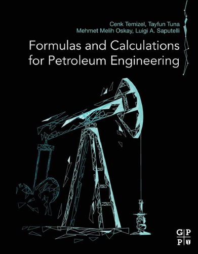
(Ebook PDF) Formulas And Calculations For Petroleum Engineering 1st Edition by Cenk Temizel, Tayfun Tuna, Mehmet Melih Oskay, Luigi Saputelli 0128165553 9780128165553 full chapters
$50.00 Original price was: $50.00.$25.00Current price is: $25.00.
Formulas And Calculations For Petroleum Engineering 1st Edition by Cenk Temizel, Tayfun Tuna, Mehmet Melih Oskay, Luigi Saputelli – Ebook PDF Instant Download/DeliveryISBN: 0128165553, 9780128165553
Full download Formulas And Calculations For Petroleum Engineering 1st Edition after payment
Product details:
ISBN-10 : 0128165553
ISBN-13 : 9780128165553
Author: Cenk Temizel, Tayfun Tuna, Mehmet Melih Oskay, Luigi Saputelli
Formulas and Calculations for Petroleum Engineering unlocks the capability for any petroleum engineering individual, experienced or not, to solve problems and locate quick answers, eliminating non-productive time spent searching for that right calculation. Enhanced with lab data experiments, practice examples, and a complimentary online software toolbox, the book presents the most convenient and practical reference for all oil and gas phases of a given project. Covering the full spectrum, this reference gives single-point reference to all critical modules, including drilling, production, reservoir engineering, well testing, well logging, enhanced oil recovery, well completion, fracturing, fluid flow, and even petroleum economics.
Formulas And Calculations For Petroleum Engineering 1st Table of contents:
Chapter 1: Reservoir engineering formulas and calculations
Abstract
1.1 API gravity
1.2 Average permeability for linear flow—Layered beds
1.3 Average permeability for linear flow—Series beds
1.4 Average permeability for parallel-layered systems
1.5 Average permeability in radial systems
1.6 Average temperature of a gas column
1.7 Calculation of fractional flow curve
1.8 Capillary number
1.9 Capillary pressure
1.10 Characteristic time for linear diffusion in reservoirs
1.11 Cole plot
1.12 Communication between compartments in tight gas reservoirs
1.13 Communication factor in a compartment in tight gas reservoirs
1.14 Compressibility drive in gas reservoirs
1.15 Correction factor—Hammerlindl
1.16 Critical rate for horizontal Wells in edge-water drive reservoirs
1.17 Crossflow index
1.18 Cumulative effective compressibility—Fetkovich
1.19 Cumulative gas production—Tarner’s method
1.20 Cumulative oil production—Undersaturated oil reservoirs
1.21 Deliverability equation for shallow gas reservoirs
1.22 Dimensionless pressure—Kamal and Brigham
1.23 Dimensionless radius of radial flow—Constant-rate production
1.24 Dimensionless time—Myhill and Stegemeier’s method
1.25 Dimensionless time for interference testing in homogeneous reservoirs—Earlougher
1.26 Dimensionless vertical well critical rate correlations—Hoyland, Papatzacos, and Skjaeveland
1.27 Dimensionless wellbore storage coefficient of radial flow—Constant-rate production
1.28 Effective compressibility in undersaturated oil reservoirs—Hawkins
1.29 Effective wellbore radius of a horizontal well—Method 1—Anisotropic reservoirs
1.30 Effective wellbore radius of a horizontal well—Method 1—Isotropic reservoirs
1.31 Effective wellbore radius of a horizontal well—van der Vlis et al. method
1.32 Effective wellbore radius of a well in presence of uniform-flux fractures
1.33 Effective wellbore radius to calculate slant well productivity—van der Vlis et al.
1.34 Estimation of average reservoir pressure—MDH method
1.35 Formation temperature for a given gradient
1.36 Fraction of the total solution gas retained in the reservoir as free gas
1.37 Fractional gas recovery below the critical desorption pressure in coal bed methane reservoirs
1.38 Free gas in place
1.39 Gas adsorbed in coal bed methane reservoirs
1.40 Gas bubble radius
1.41 Gas cap ratio
1.42 Gas cap shrinkage
1.43 Gas drive index in gas reservoirs
1.44 Gas expansion factor
1.45 Gas expansion term in gas reservoirs
1.46 Gas flow rate into the wellbore
1.47 Gas flow under laminar viscous conditions
1.48 Gas formation volume factor
1.49 Gas hydrate dissociation pressure
1.50 Gas material balance equation
1.51 Gas produced by gas expansion
1.52 Gas saturation—Water-drive gas reservoirs
1.53 Gas solubility in coalbed methane reservoirs
1.54 Geertsma’s model for porosity/transit-time relationship
1.55 Geothermal gradient
1.56 Hagen Poiseuille equation
1.57 Hagoort and Hoogstra gas flow in tight reservoirs
1.58 Hammerlindl method for gas in place
1.59 High-pressure region gas flow rate
1.60 Horizontal well breakthrough time—With gas cap or bottom water
1.61 Horizontal well critical rate correlation—Chaperon
1.62 Horizontal well critical rate correlations—Efros
1.63 Horizontal well critical rate correlations—Giger and Karcher
1.64 Horizontal well critical rate correlations—Joshi method for gas coning
1.65 Hydrocarbon pore volume occupied by evolved solution gas
1.66 Hydrocarbon pore volume occupied by gas cap
1.67 Hydrocarbon pore volume occupied by remaining oil
1.68 Hydrostatic pressure
1.69 Incremental cumulative oil production in undersaturated reservoirs
1.70 Ineffective porosity
1.71 Initial gas cap
1.72 Initial gas in place for water-drive gas reservoirs
1.73 Injectivity index
1.74 Instantaneous gas-oil ratio
1.75 Interporosity flow coefficient
1.76 Interstitial velocity
1.77 Isothermal compressibility of oil—Vasquez-Beggs correlation—P > Pb
1.78 Isothermal compressibility of oil—Villena-Lanzi correlation—P < Pb
1.79 Isothermal compressibility of water—Osif correlation
1.80 Kerns method for gas flow in a fracture
1.81 Klinkenberg gas effect
1.82 Kozeny equation
1.83 Kozeny-Carman relationship
1.84 Leverett J-function
1.85 Line-source solution for damaged or stimulated wells
1.86 Low-pressure region gas flow rate for non-circular drainage area
1.87 Material balance for cumulative water influx—Havlena and Odeh
1.88 Maximum height of oil column in cap rock
1.89 Modified Cole plot
1.90 Modified Kozeny-Carman relationship
1.91 Normalized saturation
1.92 Oil bubble radius of the drainage area of each well represented by a circle
1.93 Oil density—Standing’s correlation
1.94 Oil formation volume factor—Standing’s correlation
1.95 Oil formation volume factor—Beggs-standing correlation—P < Pb
1.96 Oil formation volume factor—Beggs-standing correlation—P > Pb
1.97 Oil in place for undersaturated oil reservoirs without fluid injection
1.98 Oil in place in saturated oil reservoirs
1.99 Oil lost in migration
1.100 Oil saturation at any depletion state below the bubble point pressure
1.101 Original gas in place
1.102 Payne method for intercompartmental flow in tight gas reservoirs
1.103 Performance coefficient for shallow gas reservoirs
1.104 Poisson’s ratio
1.105 Pore throat sorting
1.106 Pore volume occupied by injection of gas and water
1.107 Pore volume through squared method in tight gas reservoirs
1.108 Porosity determination—IES and FDC logs
1.109 Produced gas-oil ratio
1.110 Productivity index for a gas well
1.111 Pseudo-steady state productivity of horizontal Wells—Method 1
1.112 Pseudo-steady state productivity of horizontal Wells—Method 2
1.113 Pseudo-steady state productivity of horizontal wells—Method 3
1.114 Pseudo-steady state radial flow equation
1.115 Relative permeability—Corey exponents
1.116 Remaining gas in place in coalbed methane reservoirs
1.117 Roach plot for abnormally pressured gas reservoirs
1.118 Rock expansion term in abnormally pressured gas reservoirs
1.119 Shape factor—Earlougher
1.120 Solution gas oil ratio—Beggs-standing correlation—P < Pb
1.121 Solution gas oil ratio—Standing’s correlation
1.122 Solution gas water ratio
1.123 Somerton method for formation permeability in coalbed methane reservoirs
1.124 Specific gravity of gas hydrate forming components
1.125 Time to reach the semi-steady state for a gas well in a circular or square drainage area
1.126 Time to the end of infinite-acting period for a well in a circular reservoir
1.127 Torcaso and Wyllie’s correlation for relative permeability ratio prediction
1.128 Total compressibility
1.129 Total pore volume compressibility
1.130 Transmissibility between compartments
1.131 Transmissibility of a compartment
1.132 Transmissivity
1.133 Trapped gas volume in water-invaded zones
1.134 Two-phase formation volume factor
1.135 Underground fluid withdrawal—Havlena and Odeh
1.136 Vertical well critical rate correlations—Craft and Hawkins method
1.137 Vertical well critical rate correlations—Hoyland, Papatzacos, and Skjaeveland—Isotropic reservoirs
1.138 Vertical well critical rate correlations—Meyer, Gardner, and Pirson—Simultaneous gas and water coning
1.139 Vertical well critical rate correlations—Meyer, Gardner, and Pirson—Water coning
1.140 Vertical well critical rate correlations—Meyer, Gardner, and Pirson—Gas coning
1.141 Viscosibility
1.142 Viscosity of crude oil through API
1.143 Viscosity of dead oil—Standing’s correlation
1.144 Viscosity of dead-oil—Egbogah correlation—P < Pb
1.145 Viscosity of live oil—Beggs/Robinson correlation
1.146 Viscosity of oil—Vasquez/Beggs correlation—P > Pb
1.147 Viscosity of water at atmospheric pressure—McCain correlation
1.148 Viscosity of water at reservoir pressure—McCain correlation
1.149 Volume of gas adsorbed in coalbed methane reservoirs
1.150 Volumetric heat capacity of a reservoir
1.151 Water breakthrough correlation in vertical wells—Bournazel and Jeanson
1.152 Water breakthrough correlations in vertical wells—Sobocinski and Cornelius
1.153 Water content of sour gas
1.154 Water cut—Stiles
1.155 Water-drive index for gas reservoirs
1.156 Water-drive recovery
1.157 Water expansion term in gas reservoirs
1.158 Water formation volume factor—McCain correlation
1.159 Water influx—Pot aquifer model
1.160 Water influx constant for the van Everdingen and Hurst unsteady-state model
1.161 Water two-phase formation volume factor
1.162 Waxman and Smits model—Clean sands
1.163 Welge extension—Fractional flow
Chapter 2: Drilling engineering formulas and calculations
Abstract
2.1 Accumulator capacity
2.2 Accumulator precharge pressure
2.3 Amount of additive required to achieve a required cement slurry density
2.4 Amount of cement to be left in casing
2.5 Amount of mud required to displace cement in drillpipe
2.6 Angle of twist—Rod subjected to torque
2.7 Annular capacity between casing and multiple strings of tubing
2.8 Annular capacity between casing and multiple tubing strings
2.9 Annular velocity—Using circulation rate in Gpm
2.10 Annular velocity—Using pump output in bbl/min
2.11 Annular velocity for a given circulation rate
2.12 Annular velocity for a given pump output
2.13 Annular volume capacity of pipe
2.14 API water loss calculations
2.15 Area below the casing shoe
2.16 Axial loads in slips
2.17 Beam force
2.18 Bit nozzle pressure loss
2.19 Bit nozzle selection—Optimized hydraulics for two and three jets
2.20 Borehole torsion—Cylindrical helical method
2.21 Bottomhole annulus pressure
2.22 Bottomhole assembly length required for a desired weight on bit
2.23 Bulk density of cuttings—Using the mud balance
2.24 Bulk modulus using Poisson’s ratio and Young’s modulus
2.25 Buoyancy weight
2.26 Buoyancy factor
2.27 Buoyancy factor using mud weight
2.28 Calculations for the number of feet to be cemented
2.29 Calculations required for spotting pills
2.30 Capacity formulas—bbl/ft
2.31 Capacity formulas—gal/ft
2.32 Capacity of tubulars and open-hole
2.33 CO2 solubility in oil and oil-mud emulsifiers
2.34 Combined solubility—Hydrocarbon gas, CO2, and H2S—in each of the mud components
2.35 Control drilling—Maximum drilling rate
2.36 Conversion of pressure into the mud weight
2.37 Cost per foot during drilling
2.38 Cost per foot of coring
2.39 Critical annular velocity and critical flow rate
2.40 Critical flow rate for flow regime change
2.41 Critical velocity for change in flow regime
2.42 Crown block capacity
2.43 Current drag force—Offshore
2.44 Curvature radius for a borehole
2.45 Cutting slip velocity
2.46 Cuttings produced per foot of hole drilled—bbls
2.47 Cuttings produced per foot of hole drilled—lbs
2.48 D—Exponent
2.49 Depth of a washout—Method 1
2.50 Depth of a washout—Method 2
2.51 Derrick efficiency factor
2.52 Difference in pressure gradient between the cement and mud
2.53 Differential hydrostatic pressure between cement in the annulus and mud inside the casing
2.54 Dilution of a mud system
2.55 Direction of dip
2.56 Directional curvature for a deviated well
2.57 Downward force or weight of casing
2.58 Drill pipe or drill collar capacity
2.59 Drill pipe or drill collar displacement and weight
2.60 Drill string design—Drill pipe length for bottomhole assembly
2.61 Drilled gas entry rate
2.62 Drilling cost per foot
2.63 Drilling ton miles—Coring operation ton miles
2.64 Drilling ton miles—Drilling/connection ton miles
2.65 Drilling ton miles—Round trip ton miles
2.66 Drilling ton miles—While making short trip ton miles
2.67 Drilling ton miles—Setting casing ton miles
2.68 Duplex pump factor
2.69 Duplex pump output—Using liner diameter
2.70 Duplex pump output—Using rod diameter
2.71 Duplex pump output by using liner and rod diameters
2.72 Dynamically coupled linear flow—Formation invasion
2.73 Effective weight during drilling
2.74 Effective wellbore radius for finite-conductivity fractures
2.75 Effective wellbore radius in infinite-conductivity fractures
2.76 Efficiency of block and tackle system
2.77 Equivalent area of pipe subject to uniform axial force
2.78 Equivalent circulating density
2.79 Equivalent density of a wellbore fluid
2.80 Equivalent formation water resistivity from SP log
2.81 Equivalent mud weight—Deviated well
2.82 Equivalent mud weight—Vertical well
2.83 Evaluation of centrifuge
2.84 Evaluation of hydrocyclone
2.85 Fluid volume required to spot a plug
2.86 Force applied to stretch material
2.87 Force exerted by the fluid on the solid surface of flow through an annulus
2.88 Friction factor in drill pipe
2.89 Front displacement of a particle in the reservoir—Formation invasion
2.90 Gas migration velocity
2.91 Gas solubility in a mud system
2.92 Gas/mud ratio
2.93 Gel strength—Optimal solid removal efficiency
2.94 Gel strength—Solid control efficiency
2.95 Gel strength—Solids build-up in system
2.96 Height of cement in the annulus
2.97 Hydraulic horsepower
2.98 Hydraulics analysis
2.99 Hydromechanical specific energy
2.100 Hydrostatic pulling
2.101 Hydrostatic pulling wet pipe out of the hole
2.102 Hydrostatic pressure in annulus due to slug
2.103 Hydrostatic pressure decrease at total depth caused by gas-cut mud
2.104 Impact force—Nozzle hydraulic analysis
2.105 Impringing jet
2.106 Increase mud density by barite
2.107 Increase mud density by calcium carbonate
2.108 Increase mud density by hematite
2.109 Increase volume by barite
2.110 Increase volume by calcium carbonate
2.111 Increase volume by hematite
2.112 Initial volume required to achieve a volume with barite
2.113 Initial volume required to achieve a volume with calcium carbonate
2.114 Initial volume required to achieve a volume with hematite
2.115 Injection/casing pressure required to open valve
2.116 Input power of a pump—Using fuel consumption rate
2.117 Jet velocity—Nozzle hydraulic analysis
2.118 Kick analysis—Influx
2.119 Kick analysis—Formation pressure with well shut-in on a kick
2.120 Kick analysis—Maximum pit gain from a gas kick in water-based mud
2.121 Kick analysis—Maximum surface pressure from a gas kick in water-based mud
2.122 Kick analysis—Shut-in drill pipe pressure
2.123 Kick analysis—Height of influx
2.124 Kill weight mud determination—Moore equation
2.125 Kinetic friction
2.126 Laser specific energy
2.127 Lateral load imposed on a casing centralizer—Cementing
2.128 Lateral load imposed on a casing centralizer with a dogleg—Cementing
2.129 Linear annular capacity of pipe
2.130 Linear capacity of pipe
2.131 Load to break cement bond—Cementing
2.132 Mass rate of flow through annulus
2.133 Matching conditions at the cake-to-rock interface—Formation invasion
2.134 Maximum allowable mud weight
2.135 Maximum drilling rate—Larger holes
2.136 Maximum equivalent derrick load
2.137 Maximum length of a slanted well in a given reservoir thickness
2.138 Maximum length of drillpipe for a specific bottomhole assembly
2.139 Maximum recommended low-gravity solids
2.140 Maximum recommended solids fractions in drilling fluids
2.141 Maximum weight on bit
2.142 Mechanical energy balance for wellbore fluids
2.143 Mechanical specific energy
2.144 Mud rheology—Herschel and Buckley law
2.145 Mud rheology—Power-law model—Consistency index
2.146 Mud rheology—Power-law model—Power-law index
2.147 Mud rheology—Power-law
2.148 Mud rheology calculations—Bingham plastic model
2.149 Mud weight increase required to balance pressure
2.150 Mud weight reduction by dilution—Water/diesel/any liquid
2.151 Mudcake growth equation—Formation invasion
2.152 Mudcake growth equation-2—Formation invasion
2.153 Mudcake permeability—Formation invasion
2.154 New pump circulating pressure
2.155 Nozzle area calculation
2.156 Number of sacks of cement required
2.157 Number of sacks of cement required for a given length of plug
2.158 Number of sacks of lead cement required for annulus
2.159 Number of sacks of tail cement required for casing
2.160 Open-ended displacement volume of pipe
2.161 Overall efficiency—Diesel engines to mud pump
2.162 Overall power system efficiency
2.163 Penetration rate—Drill-rate model—Alternative equation
2.164 Penetration rate—Drill-rate model—Basic equation
2.165 Percentage of bit nozzle pressure loss
2.166 Plastic viscosity—Bingham plastic model
2.167 Plug length to set a balanced cement plug
2.168 Polar moment of inertia
2.169 Polished rod horsepower—Sucker-rod pump
2.170 Pore-pressure gradient—Rehm and McClendon
2.171 Pore-pressure gradient—Zamora
2.172 Pressure analysis—Pressure by each barrel of mud in casing
2.173 Pressure analysis—Surface pressure during drill stem test
2.174 Pressure gradient
2.175 Pressure required to break circulation—Annulus
2.176 Pressure required to break circulation—Drill string
2.177 Pressure required to overcome gel strength of mud inside the drill string
2.178 Pressure required to overcome mud’s gel strength in annulus
2.179 Pump calculation—Pump pressure
2.180 Pump calculations—Power required
2.181 Pump displacement
2.182 Pump flow rate
2.183 Pump head rating
2.184 Pump output—gpm
2.185 Pump output triplex pump
2.186 Pump pressure/pump stroke relationship
2.187 Radial force related to axial load—Cementing
2.188 Range of load—Sucker-Rod pump
2.189 Rate of fuel consumption by a pump
2.190 Rate of gas portion that enters the mud
2.191 Relationship between traveling block speed and fast line speed
2.192 Rock removal rate
2.193 Rotating horsepower
2.194 Side force at bit in anisotropic formation
2.195 Sinusoidal buckling
2.196 Slurry density for cementing calculations
2.197 Solids analysis—High-salt content muds
2.198 Solids analysis low-salt content muds
2.199 Spacer volume behind slurry required to balance the plug
2.200 Specific gravity of cuttings by using mud balance
2.201 Stripping/snubbing calculations—Breakover point between stripping and snubbing
2.202 Stripping/snubbing calculations—Height gain and casing pressure from stripping into influx
2.203 Stripping/snubbing calculations—Maximum Allowable surface pressure governed by casing burst pressure
2.204 Stripping/snubbing calculations—Maximum allowable surface pressure governed by formation
2.205 Stripping/snubbing calculations—Minimum surface pressure before stripping
2.206 Stripping/snubbing calculations—Constant BHP with a gas bubble rising
2.207 Stroke per minute required for a given annular velocity
2.208 Stuck pipe calculations—Method-1
2.209 Stuck pipe calculations—Method-2
2.210 Subsea considerations—Adjusting choke line pressure loss for higher mud weight
2.211 Subsea considerations—Casing burst pressure-subsea stack
2.212 Subsea considerations—Choke line pressure loss
2.213 Subsea considerations—Maximum allowable mud weight—Subsea stack from leakoff test
2.214 Subsea considerations—Casing pressure decrease when bringing well on choke
2.215 Subsea considerations—Velocity through choke line
2.216 Surface test pressure required to frac the formation
2.217 Total amount of solids generated during drilling
2.218 Total heat energy consumed by the engine
2.219 Total number of sacks of tail cement required
2.220 Total water requirement per sack of cement
2.221 Triplex pump factor
2.222 Upward force acting at the bottom of the casing shoe
2.223 Vertical curvature for deviated wells
2.224 Viscous shear stress at the outer mudcake boundary
2.225 Volume of cuttings generated per foot of hole drilled
2.226 Volume of dilution water or mud required to maintain circulating volume
2.227 Volume of fluid displaced for duplex pumps
2.228 Volume of fluid displaced for single-acting pump
2.229 Volume of fluid displaced for triplex pump
2.230 Volume of liquid (oil plus water) required to prepare a desired volume of mud
2.231 Volume of slurry per sack of cement
2.232 Volumes and strokes—Annular volume
2.233 Volumes and strokes—Drill string volume
2.234 Volumes and strokes—Total strokes
2.235 Weight of additive per sack of cement
2.236 Weighted cementing calculations
Chapter 3: Well test analysis formulas and calculations
Abstract
3.1 Analysis of a flow test with smoothly varying rates
3.2 Analysis of a post-fracture—Constant-rate flow test with boundary effects
3.3 Analysis of a post-fracture pressure buildup test with wellbore-storage distortion
3.4 Analysis of a well from a PI test
3.5 Analysis of DST flow data with Ramey type curves
3.6 Average fracture permeability (pseudo-steady state case for pressure build-up test)
3.7 Bottomhole flowing pressure during infinite-acting pseudoradial flow
3.8 Calculation of pressure beyond the wellbore (line-source solution)
3.9 Conventional DST design without a water cushion (collapse pressure calculation)
3.10 Diffusion depth in a geothermal well
3.11 Dimensionless buildup pressure for field calculations
3.12 Dimensionless buildup pressure for liquid flow
3.13 Dimensionless buildup pressure for steam or gas flow
3.14 Dimensionless buildup time
3.15 Dimensionless cumulative production (radial flow constant-pressure production)
3.16 Dimensionless drawdown correlating parameter by Carter
3.17 Dimensionless length (linear flow constant rate production/hydraulically fractured wells)
3.18 Dimensionless length (linear flow/constant-rate production/general case)
3.19 Dimensionless pressure (linear flow/constant rate production/general case)
3.20 Dimensionless pressure (linear flow/constant rate production/hydraulically-fractured wells)
3.21 Dimensionless pressure (radial-flow/constant pressure production)
3.22 Dimensionless pressure (radial-flow/constant rate production)
3.23 Dimensionless pressure drop across a skin at the well face
3.24 Dimensionless pressure drop during pseudo-steady state flow for a fractured vertical well in a square drainage area
3.25 Dimensionless pressure drop during pseudo-steady state flow for a horizontal well in a bounded reservoir
3.26 Dimensionless production time
3.27 Dimensionless rate (radial flow/constant pressure production)
3.28 Dimensionless shut-in time for MDH method
3.29 Dimensionless storage constant for gases
3.30 Dimensionless storage constant for liquids
3.31 Dimensionless time (linear flow/constant rate production/general case)
3.32 Dimensionless time (linear flow/constant rate production/hydraulically fractured wells)
3.33 Dimensionless time (radial flow/constant rate production)
3.34 Dimensionless time function (transient heat transfer to the formation)
3.35 Dimensionless wellbore storage coefficient (compressible fluids for pressure build-up test)
3.36 Flow period duration (hydraulically fractured wells)
3.37 Fracture conductivity (bilinear-flow regime in gas wells)
3.38 Fracture conductivity during bilinear flow
3.39 Inflow performance relationship (IPR) for horizontal wells in solution gas-drive reservoirs (Fetkovich)
3.40 Inflow performance relationship (IPR) for horizontal wells in solution gas-drive reservoirs (Vogel)
3.41 Interporosity flow coefficient in pressure build-up test
3.42 Minimum shut-in time to reach pseudo-steady state for tight gas reservoirs being hydraulically fractured
3.43 Permeability and reservoir pressure from buildup tests
3.44 Permeability and skin factor from a constant-rate flow test
3.45 Pressure buildup equation (Horner equation)
3.46 Radius of investigation
3.47 Radius of investigation (flow time)
3.48 Radius of investigation (shut-in time)
3.49 Raymer hunt transform (porosity/transit time relationship)
3.50 Reservoir permeability
3.51 Shut-in time for pressure build-up test (Dietz method)
3.52 Skin during infinite-acting pseudoradial flow for vertical wells
3.53 Skin estimation type-1 (pressure buildup test)
3.54 Slope of Horner plot in pressure buildup test
3.55 Slope of pseudo-steady state flow in pressure buildup test
3.56 Time to pseudo-steady state (single well-circular reservoir)
3.57 Time to reach the semi-steady state for a gas well in a circular or square drainage area
3.58 True wellbore storage coefficient (pressure build-up test)
3.59 Well flow efficiency (geothermal well)
3.60 Well shut-in pressure during buildup (Horner plot)
Chapter 4: Production engineering formulas and calculations
Abstract
4.1 Acid penetration distance (acidizing)
4.2 Additional pressure drop in the skin zone
4.3 Additive crystalline salt amount to increase the density—Method I (single-salt systems)
4.4 Additive crystalline salt amount to increase the density—Method II (single-salt systems)
4.5 Additive crystalline salt and water amount to increase the density—Method I (two-salt systems)
4.6 Annulus pressure loss due to friction during hydraulic fracturing (laminar flow)
4.7 Annulus pressure loss due to friction during hydraulic fracturing (turbulence flow)
4.8 Approximate ideal counterbalanced load
4.9 Average downstroke load (sucker-rod pump)
4.10 Average fracture width (acidizing)
4.11 Average permeability of a hydraulically fractured formation
4.12 Average specific weight of the formation (hydraulic fracturing)
4.13 Average upstroke load (sucker-rod pump)
4.14 Average wellbore fluid density (completion and workover fluids)
4.15 Capacity ratio of a hydraulically fractured surface
4.16 Choke discharge coefficient
4.17 Close-ended displacement volume of pipe
4.18 Convective mass transfer for laminar flow (acidizing)
4.19 Convective mass transfer for turbulent flow (acidizing)
4.20 Correct counterbalance (sucker-rod pump)
4.21 Corresponding reciprocal rate (post-fracture production—Constant Bottomhole flowing conditions)
4.22 Damaged/undamaged zone productivity comparison (acidizing)
4.23 Density of brine (completion and workover fluids)
4.24 Dimensionless fracture width for linear vertical fracture (Geertsma & Klerk)
4.25 Downhole operating pressure (hydraulic fracturing)
4.26 Entrance hole size (perforation)
4.27 Equivalent skin factor in fractured wells
4.28 Filter cake on the fracture (acidizing)
4.29 Flow coefficient during drawdown
4.30 Flow rate through orifice
4.31 Flow through fracture in response to pressure gradient
4.32 Formation fluid compressibility (acidizing)
4.33 Fracture area of a hydraulically fractured formation
4.34 Fracture coefficient of a hydraulically fractured reservoir
4.35 Fracture fluid coefficient for reservoir-controlled liquids
4.36 Fracture fluid coefficient for viscosity-controlled liquids
4.37 Fracture geometry (acidizing)
4.38 Fracture gradient (hydraulic fracturing)
4.39 Fracture-fluid invasion of the formation (acidizing)
4.40 Frictional pressure drop (Economides and Nolte)
4.41 Gas velocity under sonic flow conditions (through choke)
4.42 Hydraulic fracture efficiency
4.43 Hydraulic horse power for a hydraulic fracturing operation
4.44 Ideal fracture conductivity created by acid reaction (acidizing)
4.45 Incremental density in any wellbore interval (completion and workover fluids)
4.46 Initial rate following a hydraulic fracturing operation
4.47 Injection pressure for hydraulic fracturing
4.48 Lifetime of a hydraulically fractured well
4.49 Mass of rock dissolved per unit mass of acid (acidizing)
4.50 Mass transfer in acid solutions by Fick’s law (acidizing)
4.51 Maximum treatment pressure (hydraulic fracturing)
4.52 Mechanical resistant torque (PCP)
4.53 Minimum polished rod load (sucker rod pump)
4.54 Peclet number for fluid loss (acidizing)
4.55 Perforation friction factor
4.56 Perforation friction pressure
4.57 Perforation hole size (perforation)
4.58 Perforation length in formation
4.59 Perforation penetration ratio (formation of interest/reference formation)
4.60 Perforation skin factor
4.61 Pore growth function (acidizing)
4.62 Pressure drop across perforations in gas wells
4.63 Pressure drop across perforations in oil wells
4.64 Pressure loss due to perforations during hydraulic fracturing
4.65 Pressure loss due to perforations during hydraulic fracturing—2
4.66 Principal stress due to petro-static pressure (hydraulic fracturing)
4.67 Productivity index (for generating composite IPR curve)
4.68 Productivity ratio
4.69 Productivity ratio calculation of a hydraulically-fractured formation
4.70 Pseudo skin factor due to partial penetration (Brons and Marting method)
4.71 Pseudo-skin factor due to partial penetration (Yeh and Reynolds correlation)
4.72 Pseudo-skin factor due to partial penetration (Odeh correlation)
4.73 Pseudo-skin factor due to partial penetration (Papatzacos correlation)
4.74 Pseudo-skin factor due to perforations
4.75 Quantifying formation damage and improvement
4.76 Recommended underbalanced environment for perforation
4.77 Reynolds number for acid flow into the fracture (acidizing)
4.78 Reynolds number for fluid loss (acidizing)
4.79 Sand weight needed to refill a hydraulically fractured reservoir volume
4.80 Shape factor expressed as skin factor for vertical wells
4.81 Single-phase gas flow (subsonic)
4.82 Single-phase liquid flow through choke
4.83 Skin factor
4.84 Skin factor by Hawkins method
4.85 Skin factor due to partial penetration
4.86 Skin factor due to reduced crushed-zone permeability
4.87 Skin factor for a deviated well
4.88 Slope of Semilog plot for bottom-hole flowing pressure vs time for drawdown test
4.89 Sucker rod—Peak polished rod load
4.90 Suspension property of static fluids (completion and workover fluids)
4.91 Tangential annular flow of a power law fluid
4.92 Temperature at choke outlet
4.93 The z component of the force of the fluid on the wetted surface of the pipe
4.94 Total skin in partially depleted wells for a buildup test
4.95 Velocity distribution in the annular slit of a falling-cylinder viscometer
4.96 Velocity distribution in the narrow annular region in annular flow with inner cylinder moving axially
4.97 Velocity distribution of flow through an annulus
4.98 Velocity of fluid in annulus
4.99 Velocity of fluid in pipe
4.100 Viscous force acting on the rod over the narrow annular region
4.101 Volume capacity of pipe
4.102 Volume of fluid loss per unit area measured in a dynamic test (acidizing)
4.103 Volume of fluid loss per unit area measured in a static test (acidizing)
4.104 Volume of rock dissolved per unit volume of acid (acidizing)
4.105 Water quantity that dilutes the original brine with assumed density (two-salt systems)
4.106 Weight of crystalline CaCl2 and CaBr2 salt addition to brine (two-salt systems)
4.107 Well flowing pressure (line-source solution by including skin factor)
4.108 Well flowing pressure under Pseudo-steady state flow for non-circular reservoirs
4.109 Wellbore pressure loss due to friction during hydraulic fracturing (laminar flow)
4.110 Wellbore pressure loss due to friction during hydraulic fracturing (turbulence flow)
4.111 Wellbore storage
4.112 Wellbore storage due to fluid level
4.113 Wellhead pressure (multiphase flow across the choke)
4.114 Workover operations (maximum allowed tubing pressure)
4.115 Young Modulus by using sonic travel time (acidizing)
Chapter 5: Fluid flow and transport phenomena formulas and calculations
Abstract
5.1 Archimedes number
5.2 Average number of collisions to reduce neutron energy
5.3 Average velocity of a falling film with variable viscosity
5.4 Average velocity of flow through a circular tube
5.5 Average velocity of flow through an annulus
5.6 Average velocity of fluids in flow of two adjacent immiscible fluids
5.7 Average velocity over the cross section of a falling film
5.8 Blowdown time in unsteady gas flow
5.9 Boltzmann equation
5.10 Boussinesq approximation—Buoyancy
5.11 Brinkman number
5.12 Buckingham Reiner equation
5.13 Calculation of mass flow rate
5.14 Calculation of momentum flux
5.15 Combined momentum flux tensor
5.16 Combined radiation and convection
5.17 Compressible flow in a horizontal circular tube
5.18 Compton scattering
5.19 Correction factor for stagnant film according to the penetration model
5.20 Darcy Weisbach equation (head loss form)
5.21 Darcy Weisbach equation (pressure loss form)
5.22 Dean number
5.23 Deborah number
5.24 Decay of thermal neutrons
5.25 Determination of the controlling resistance
5.26 Determination of the diameter of a falling sphere
5.27 Diffusion from an instantaneous point source
5.28 Diffusion in a moving film
5.29 Diffusion in polymers
5.30 Diffusion Into a falling liquid film (gas absorption)
5.31 Diffusion of low-density gases with equal mass
5.32 Diffusion potential
5.33 Diffusion through a non-isothermal spherical film
5.34 Diffusion through a stagnant film
5.35 Diffusion through a stagnant gas film
5.36 Diffusion through cleat spacing in coalbed methane reservoirs
5.37 Diffusion with a heterogeneous chemical reaction
5.38 Diffusion with a homogeneous chemical reaction
5.39 Diffusion, convection, and chemical reaction
5.40 Drag coefficient
5.41 Drag force
5.42 Draining of a cylindrical tank
5.43 Draining of a spherical tank
5.44 Eckert number
5.45 Effective emissivity of a hole
5.46 Effective thermal conductivity for a solid with spherical inclusions
5.47 Efflux time for draining a conical tank
5.48 Ekman number
5.49 Elimination of circulation in a rising gas bubble
5.50 Energy emitted from the surface of a black body
5.51 Estimation of diffusivity of liquids
5.52 Estimation of self diffusivity at high density
5.53 Estimation of the viscosity of a pure liquid
5.54 Euler number
5.55 Fanning friction factor (laminar flow)
5.56 Fanning’s friction factor (turbulent flow)
5.57 Fick’s law of binary diffusion
5.58 Film condensation on vertical pipes
5.59 Film condensation on vertical tubes
5.60 Film thickness of a falling film on a conical surface
5.61 Flow in a liquid-liquid ejector pump
5.62 Flow in a slit with uniform cross flow
5.63 Flow near a corner
5.64 Flow of power law fluid through a narrow slit
5.65 Fluid kinetic force in conduits
5.66 Fluid kinetic force in flow around submerged objects
5.67 Form drag
5.68 Free air correction—Gravity survey
5.69 Free batch expansion of a compressible fluid
5.70 Free convection heat transfer from a vertical plate
5.71 Friction drag
5.72 Friction factor for creeping flow around a sphere
5.73 Friction factor in flow around submerged objects
5.74 Friction factor in flow through conduits
5.75 Friction factor in packed column (laminar)
5.76 Friction factor in packed column (turbulant)
5.77 Galilei number
5.78 Gas absorption from rising bubbles for creeping flow
5.79 Gas absorption through bubbles
5.80 Gas absorption with chemical reaction in an agitated tank
5.81 Gas absorption with rapid reaction
5.82 Gas mass rate flow in compressible tube flow
5.83 Graetz number
5.84 Graham equation viscosity ratio
5.85 Grash of number
5.86 Hagen number
5.87 Hagen-Poiseuille equation
5.88 Influence of changing interfacial area on mass transfer
5.89 Knudsen flow
5.90 Krieger Dougherty equation viscosity ratio
5.91 Laminar flow along a flat plate (approximate solution)
5.92 Laminar flow of an incompressible power-law fluid in a circular tube
5.93 Laplace number
5.94 Lewis number
5.95 Mach number
5.96 Manning formula
5.97 Marangoni number
5.98 Mass absorption (attenuation) coefficient
5.99 Mass flow rate as a function of the modified pressure drop in a network of tubes
5.100 Mass flow rate in a rotating cone pump
5.101 Mass rate of flow
5.102 Mass rate of flow in a squared duct
5.103 Mass rate of flow of a falling film
5.104 Mass rate of flow through a circular tube
5.105 Mass transfer for creeping flow around a gas bubble
5.106 Mass transfer to drops and bubbles
5.107 Maximum flow rate (Vogel’s equation)
5.108 Maximum velocity of a falling film
5.109 Maximum velocity of flow through a circular tube
5.110 Maximum-velocity Vz-maximum of a falling film
5.111 Method for separating helium from natural gas
5.112 Modified capillary number
5.113 Modified Van Driest equation
5.114 Momentum flux distribution of flow through a circular tube
5.115 Momentum flux distribution of flow through an annulus
5.116 Momentum flux profile of fluids in flow of two adjacent immiscible fluids
5.117 Momentum fluxes for creeping flow into a slot
5.118 Mooney equation viscosity
5.119 Non-Newtonian flow in annulus
5.120 Nusselt number
5.121 Ohnesorge number
5.122 Potential flow around a cylinder
5.123 Prandtl number
5.124 Pressure distribution in a creeping flow around a sphere
5.125 Pressure drop per length of the adsorption unit
5.126 Pressure loss due to sudden enlargement
5.127 Reynolds number
5.128 Schmidt number
5.129 Sherwood number
5.130 Slit flow in Bingham fluid
5.131 Smoluchowski equation
5.132 Stanton number
5.133 Stefan number
5.134 Stokes number
5.135 Strouhal number
5.136 Taylor dispersion (axial dispersion coefficient)
5.137 Taylor equation viscosity
5.138 Taylor number
5.139 Theory of diffusion in colloidal suspensions
5.140 Toricelli equation
5.141 Total force of the fluid on the sphere in a creeping flow around a sphere
5.142 Velocity distribution in a creeping flow around a sphere
5.143 Velocity distribution of a falling film with variable viscosity
5.144 Velocity distribution of flow through a circular tube
5.145 Velocity profile of fluids in flow of two adjacent immiscible fluids
5.146 Viscosity by a falling-cylinder viscometer
5.147 Winsauer equation
Chapter 6: Well log analysis, geophysics, petrophysics formulas, and calculations
Abstract
6.1 Acoustic transit time
6.2 Amplitude transmission coefficient in seismic reflection and refraction
6.3 Apparent intensity reflected by recorder (gamma ray)
6.4 Apparent resistivity
6.5 Apparent sorption compressibility
6.6 Atlas wireline neutron lifetime log
6.7 Barenblatt-Chorin universal velocity distribution
6.8 Coefficient of reflection
6.9 Compaction correction factor for sonic logs in shale lithology
6.10 Composite capture cross section of the formation (Schlumberger thermal decay time tool)
6.11 Correlation of mud cake resistivity to mud resistivity
6.12 Correlation of mud filtrate resistivity to mud resistivity
6.13 Diffuse-layer thickness
6.14 Effect of clay on conductivity
6.15 Effective photoelectric absorption cross section index
6.16 Electric resistance to a radial current from a wellbore
6.17 Electrochemical potential (SP log)
6.18 Electrokinetic potential (developed across a mud cake)
6.19 Electron density index (GR absorbtion logging)
6.20 Epithermal neutron diffusion coefficient
6.21 Epithermal neutron distribution (epithermal neutron flux)
6.22 Fertl and Hammack equation
6.23 Formation conductivity in dual water model
6.24 Formation factor—Archie’s equation
6.25 Formation factor (Archie’s equation with resistivity logs)
6.26 Formation resistivity and permeability (Carothers) relation for limestones
6.27 Formation resistivity and permeability (Carothers) relation for sandstones
6.28 Formation resistivity and porosity relations for carbonate rocks
6.29 Formation resistivity and porosity relations from well log data based on Porter and Carothers data
6.30 Fraction of total porosity occupied by clays
6.31 Fresh water-filled porosity (fresh-water-bearing limestones)
6.32 Fxo/Fs approach
6.33 Gamma ray log shale index
6.34 General form of the Archie equation—Water saturation from resistivity logs
6.35 Generalized relationship between formation resistivity factor and porosity (Chevron formula)
6.36 Geometric coefficient for the electrode
6.37 Geometric coefficient for the lateral device
6.38 Geometric coefficient for the normal sonde
6.39 Half thickness value
6.40 Hingle nonlinear-resistivity/linear-porosity crossplot
6.41 Humble equation (formation resistivity factor vs porosity)
6.42 Integrated radial geometric factor
6.43 Lennard Jones potential
6.44 Linear absorption (attenuation) coefficient
6.45 Maximum potential for self-potential (SP) log
6.46 Mean free path (photon absorption)
6.47 Membrane potential
6.48 Neutron lethargy (logarithmic energy decrement)
6.49 Neutron porosity of shale zone
6.50 Oil saturation determination (IE and CDN logs)
6.51 Pair production (gamma ray interactions)
6.52 Phillips equation (sandstones)
6.53 Photoelectric absorption cross sectional area
6.54 Pickett crossplot
6.55 Poisson’s ratio (seismic arrival time method)
6.56 Porosity by using density log data
6.57 Porosity corrected for gas effect
6.58 Porosity-neutron flux relationship
6.59 Rate of radioactive decay
6.60 Relation between concentration of K, Th, or U and recorded total gamma ray signal
6.61 Relationship between rock resistivity and water saturation
6.62 Relationship between SSP and Rw (NaCl predominant)
6.63 Relationship between SSP and Rw (non-ideal shale membrane)
6.64 Relationship between SSP and Rw for water containing salts (non-NaCl predominant)
6.65 Resistivity of a partially saturated shaly sand with hydrocarbons (Vsh models)
6.66 Resistivity of a water-saturated shaly sand (Vsh models)
6.67 Rock conductivity (relatively clean water bearing rocks)
6.68 Shale index from gamma ray spectrometry
6.69 Simandoux (total shale) equation
6.70 Sonic porosity (Raymer Hunt Gardner method)
6.71 Spacing between transmitter and receiver
6.72 Static self potential
6.73 Time between the initiation of the pulse and the first arrival acoustic energy at the receiver
6.74 Time-average relation in compacted formations (porosity/transit time relationships)
6.75 Time-average relation in uncompacted formations (porosity/transit time relationships)
6.76 Tortuosity (resistivity logs)
6.77 Total rock conductivity
6.78 True porosity from sonic log (corrected for compaction)
6.79 True resistivity—Archie
6.80 Volumetric photoelectric absorption cross section
6.81 Water salinity index ratio
6.82 Water saturation determination (IE and CDN logs)
6.83 Water saturation from neutron tools
6.84 Water saturation—Resistivity logs
6.85 Wavelength equation
6.86 Wellbore electric voltage generation
Chapter 7: Petroleum economics formulas and calculations
Abstract
7.1 Acceptable reliability level
7.2 Additional production estimation with new wells
7.3 Annual gross revenue after royalties and wellhead taxes
7.4 Annuity from future value
7.5 Annuity from present value
7.6 Average annual rate of return method
7.7 Average book rate of return method
7.8 Calculation of unknown interest rate
7.9 Compound interest
7.10 Cost depletion
7.11 Cumulative interest on operational expenses during the lifetime of a well
7.12 Effective interest rate for periodic compounding
7.13 Exploration efficiency
7.14 Future value of an annuity
7.15 Future value of present sum
7.16 Generalized expected value calculation
7.17 Growth rate of return for continuous compounding
7.18 Hoskold method for annual rate of return prediction-1
7.19 Hoskold method for annual rate of return prediction-2
7.20 Initial capital needed to survive in a minimum chance scenario
7.21 Meterage model
7.22 Minimum number of jobs to survive in a minimum chance scenario
7.23 Minimum profit ratio per a risky job
7.24 Net cash flow
7.25 Net present value
7.26 Operating cash income
7.27 Payback Period
7.28 Present value of an annuity
7.29 Present value of a deferred annuity
7.30 Present value of future sum
7.31 Present value of profit/investment ratio for an oil well
7.32 Present value of uniform gradient series
7.33 Present worth expectation for a risky job
7.34 Probability of an oilfield discovery
7.35 Profitability index
7.36 Rate of growth per unit of exploration length
7.37 Simple interest
7.38 Total expected additional production discovery
7.39 Total expected additional production discovery in constant production per unit area
7.40 Total new production area estimation expected to be discovered
Chapter 8: Phase behavior and thermodynamics formulas and calculations
Abstract
8.1 Amount of heat required to increase the temperature
8.2 Benedict-Webb-Rubin PVT equation
8.3 Critical pressure Cavett relation
8.4 Critical temperature Cavett method
8.5 Effective thermal conductivity of composite solids
8.6 Einstein equation effective viscosity
8.7 Equilibrium vaporization ratio
8.8 Equilibrium vaporization ratio of heptane
8.9 Evaporation loss from an oxygen tank
8.10 Expansion factor for diffuse layer
8.11 Flat-plate boundary layer model
8.12 Freezing of a spherical drop
8.13 General thermal conductivity
8.14 Heat conduction in a cooling fan
8.15 Heat flux distribution in a wall
8.16 Heat loss by free convection from a horizontal pipe
8.17 Heat released during in-situ combustion given by Burger & Sahuquet
8.18 Heat transfer coefficient for condensation—Pure vapors on solid surface
8.19 Heat transfer in packed bed
8.20 Heat transfer rate in laminar forced convection along heated flat plate
8.21 Jacoby aromaticity factor
8.22 Joule Thompson expansion
8.23 Latent heat of hydrocarbon mixture
8.24 Mixing fluids of different densities
8.25 Mole fraction of a component in liquid phase
8.26 Mole fraction of a component in vapor phase
8.27 Necessary inhibitor concentration required in liquid phase to reduce hydrate point
8.28 Peng Robinson characterization factor
8.29 Peng Robinson PVT equation
8.30 Pseudo-reduced conditions
8.31 Radiant heat transfer between disks
8.32 Radiated energy flux
8.33 Radiation across an annular gap
8.34 Radiation shields
8.35 Rayleigh number
8.36 Redlich-Kwong PVT equation
8.37 Reservoir gas density
8.38 Stefan-Boltzmann law
8.39 Surface temperature of a heating coil
8.40 Temperature due to free convection
8.41 Temperature increase due to forced convection
8.42 Temperature profile after viscous heat transfer
8.43 Temperature profile with a nuclear heat source
8.44 Thermal conductivity for pure metals
8.45 Thermal conductivity of polyatomic gases
8.46 Thermal conductivity of liquids
8.47 Thermal conductivity of solids with gas pockets
8.48 Thermal diffusivity
8.49 Thermal energy of a fissionable substance
8.50 Thermoelastic effect on stress
8.51 Unsteady evaporation of a liquid
8.52 Van Der Waals PVT equation
8.53 Wien displacement law
Chapter 9: Petroleum engineering laboratory formulas and calculations
Abstract
9.1 Absolute viscosity for Saybolt viscosimeter measurements
9.2 Absolute viscosity for Ubbelohde viscosimeter measurements
9.3 Adhesion tension
9.4 Amott-Harvey wettability index
9.5 Apparent facial tension (De Nouy ring method)
9.6 Average compressibility of oil
9.7 Average gas solubility
9.8 Characterization factor for oil distillation
9.9 Clasius-Clapeyron equation for water vapor
9.10 Clay concentration of drilling mud (methylene blue test)
9.11 Contact angle
9.12 Correction factor for facial tension (De Nouy ring method)
9.13 Drilling mud density (solid content analysis of drilling muds)
9.14 Effective porosity
9.15 Error percentage of porosity measurements
9.16 Facial tension (De Nouy ring method)
9.17 Filtration rate for API fluid loss measurement
9.18 Filtration volume without spurt loss
9.19 Filtration volume with spurt loss
9.20 Gas permeability measurement (lab measurement using Klinkenberg effect)
9.21 Kinematic viscosity for Saybolt viscosimeter measurements
9.22 Liquid permeability (permeameter lab measurement)
9.23 Permeability determination using porosity data (Kozeny-Carman equation)
9.24 Pycnometer volume correction
9.25 Relative centrifugal force
9.26 Relative permeability
9.27 Reservoir wettability characterization (rise in core method)
9.28 Resistance
9.29 Resistivity
9.30 Resistivity index—Archie’s law
9.31 Solid content ratio of drilling mud
9.32 Specific gravity of air (upper phase) (De Nouy ring method)
9.33 Standard discharge time for Saybolt viscosimeter measurements
9.34 Total porosity
9.35 USBM wettability index
9.36 Yield of clays as drilling fluids
Chapter 10: Enhanced oil recovery and geothermal formulas and calculations
Abstract
10.1 Areal extent of heated zone
10.2 Average reservoir temperature in a cyclical steam injection process
10.3 Bottomhole pressure in a static geothermal well
10.4 Chromatographic lag in polymer flooding
10.5 Cumulative heat injected for steam drive—Myhill and Stegemeier
10.6 Depth of carbon dioxide alteration front (Battlet-Gouedard, 2006)
10.7 Depth of carbon dioxide alteration front (Kutchko, 2008)
10.8 Dimensionless heat injection rate (Gringarten and Sauty)
10.9 Dimensionless injection rate of air for in-situ combustion
10.10 Dimensionless ratio of effective volumetric heat capacity of injected steam to that of the steam zone
10.11 Dimensionless time for semi-steady state flow in coal bed methane reservoirs
10.12 Dimensionless time in wet combustion by Kuo
10.13 Dykstra-Parsons coefficient
10.14 Effective (apparent) transmissivity
10.15 Effective oil transmissivity for thermal stimulation
10.16 Equivalent atomic H/C ratio of fuel for in-situ combustion
10.17 Equivalent volume of steam injected—Myhill and Stegemeier
10.18 Equivalent water saturation in burned zone in-situ combustion by Nelson
10.19 Estimates of cumulative oil displacement
10.20 Estimates of oil displacement rate
10.21 Estimating fraction of heat injected in latent form (steam-drive)
10.22 Estimating heat injection rate (steam-drive)
10.23 Estimating performance prediction of steam-drive reservoirs (cumulative oil produced)
10.24 Estimating recovery steam drive (volume of steam in reservoir)
10.25 Estimating steady-state five-spot injection rate (steam-drive)
10.26 Estimating volume of steam injection (steam-drive)
10.27 Fraction of heat injected in latent form—Myhill and Stegemeier
10.28 Fraction of injected heat remaining in reservoir
10.29 Fractional flow of water in hot floods dependent on temperature and saturation in hot water flood
10.30 Growth of steam-heated area—Marx-Langenheim
10.31 Heat loss over an incremental length of a well (two-phase flow)
10.32 Heat ratio of contents in a geothermal reservoir
10.33 Heat released during in-situ combustion—Burger & Sahuguet
10.34 Heat remaining in reservoir—Marx and Langenheim
10.35 Horizontal well breakthrough time in a bottom-water-drive reservoir
10.36 Ignition delay time in in-situ combustion
10.37 Injected air required to burn through unit bulk of reservoir for in-situ combustion by Nelson and McNiel
10.38 Mass of fuel burned per unit bulk reservoir volume combustion—Nelson and McNiel
10.39 Minimum air flux required for advance of fire front—Nelson and McNiel
10.40 Oil breakthrough newly swept zone
10.41 Oil recovery as a function of the fraction of oil displaced from heated zone
10.42 Oil solubilization factor
10.43 Oil volume at breakthrough by Craig, Geffen, and Morse
10.44 Oil-steam ratio—Marx & Langenheim
10.45 Proppant settlement in fracture
10.46 Rate of advancement of combustion front (in-situ combustion)
10.47 Rate of growth of heated zone in hot water heated reservoir
10.48 Rate of oxygen-reacted per unit mass of fuel
10.49 Relationship with real and dimensionless time in hot water floods
10.50 Reservoir flow for gas flow in a formation
10.51 Reservoir flow through the wellbore of a geothermal well
10.52 Saturation of layer under hot water flood
10.53 Slug size in polymer floods
10.54 Temperature increase with time during in-situ combustion process
10.55 Temperature of a producing geothermal well
10.56 Temperature of a single-phase liquid or gas injected geothermal well
10.57 Total heat loss of a geothermal well
10.58 Total oil production from in-situ combustion—Nelson & McNeil
10.59 Total oil production from wet in-situ combustion—Nelson & McNeil
10.60 Total water production from in-situ combustion—Nelson & McNeil
10.61 Volume of burned part of reservoir (in-situ combustion)
10.62 Volume of reservoir burnt by wet combustion
10.63 Volumetric heat capacity
10.64 Wet combustion design (in-situ combustion)
People also search for Formulas And Calculations For Petroleum Engineering 1st:
oilfield calculations and formulas
engineering calculations and formulas
petroleum engineering equations
petroleum formula
petroleum engineering formulas
Tags:
Formulas,Calculations,Petroleum Engineering,Cenk Temizel,Tayfun Tuna,Mehmet Melih Oskay,Luigi Saputelli
You may also like…
Engineering - Chemical Engineering
Uncategorized
Nanocolloids for Petroleum Engineering: Fundamentals and Practices 1st edition Baghir Suleimanov
Computers - Applications & Software
Engineering
Computers - Applications & Software
Up Up and Array!: Dynamic Array Formulas for Excel 365 and Beyond 1st Edition
Engineering - Energy & Power Resources
Methods and Applications in Petroleum and Mineral Exploration and Engineering Geology Said Gaci


