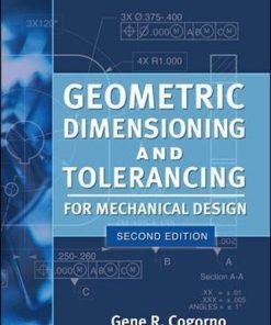
Geometric Dimensioning and Tolerancing for Mechanical Design 1st edition by Gene Cogorno 1260453790 9781260453799
$50.00 Original price was: $50.00.$25.00Current price is: $25.00.
Geometric Dimensioning and Tolerancing for Mechanical Design 1st edition by Gene R. Cogorno – Ebook PDF Instant Download/DeliveryISBN: 1260453790, 9781260453799
Full download Geometric Dimensioning and Tolerancing for Mechanical Design 1st edition after payment.

Product details:
ISBN-10 : 1260453790
ISBN-13 : 9781260453799
Author : Gene R. Cogorno
Publisher’s Note: Products purchased from Third Party sellers are not guaranteed by the publisher for quality, authenticity, or access to any online entitlements included with the product. A fully updated guide to geometric dimensioning and tolerancing This thoroughly revised engineering textbook teaches the principles and practices of geometric dimensioning and tolerancing in a straightforward, easy-to-follow manner. Written in accordance with the latest revision to the GD&T standard, ASME Y14.5-2018, Geometric Dimensioning and Tolerancing for Mechanical Design, Third Edition shows, step by step, how to improve quality, lower cost, and shorten delivery times. You will get clear definitions along with detailed discussions on how each geometric control is specified, interpreted, and inspected. Detailed drawings and examples illustrate each concept. Up-to-date coverage includes: • Dimensioning and tolerancing fundamentals • Symbols, terms, and rules • Datums • Form—flatness, straightness, circularity and cylindricity • Orientation—perpendicularity, parallelism, and angularity • Position—general functions and location applications • Coaxiality • Runout • Profile • Strategy for tolerancing parts • Graphic analysis • And more
Geometric Dimensioning and Tolerancing for Mechanical Design 1st Table of contents:
1 Introduction to Geometric Dimensioning and Tolerancing
Chapter Objectives
What Is GD&T?
When Should GD&T Be Used?
Advantages of GD&T over Coordinate Dimensioning and Tolerancing
The Cylindrical Tolerance Zone
The Maximum Material Condition Modifier
Datum Features Specified in Order of Precedence
Summary
Chapter Review
2 Dimensioning and Tolerancing Fundamentals
Chapter Objectives
Fundamental Drawing Rules
Units of Linear Measurement
Specifying Linear Dimensions
Specifying Linear Tolerances
Interpreting Dimensional Limits
Specifying Angular Dimensions
Specifying Angular Tolerances
Dimensioning and Tolerancing for CAD/CAM Database Models
Summary
Chapter Review
3 Symbols, Terms, and Rules
Chapter Objectives
Symbols
Geometric Characteristic Symbols
The Datum Feature Symbol
The Feature Control Frame
Reading the Feature Control Frame
Attaching a Feature Control Frame to a Feature
Other Symbols Used with Geometric Tolerancing
Terms
Rules
Rule #1: Limits of Size Prescribe Variations of Form
Rule #2: Applicability of Modifiers in Feature Control Frames
The Pitch Diameter Rule
Summary
Chapter Review
Problems
4 Datums
Chapter Objectives
Definition of a Datum
Application of Datums
Immobilization of a Part
A Datum Reference Frame Provides Origin and Direction
Datum Feature Selection
Datum Feature Identification
Inclined Datum Features
Cylindrical Datum Features
Establishing Datum Features
Plane Flat Surfaces Specified as Datum Features
Datum Features of Size at RMB
Datum Features of Size at MMB
Plane Flat Surfaces versus Features of Size
Irregular Datum Features of Size
Common Datum Features
Partial Datum Features
Datum Targets
Datum Targets Established on a Cylindrical Part
Step Datum Targets and Movable Datum Target Symbols
Summary
Chapter Review
Problems
5 Form
Chapter Objectives
Flatness
Definition
Specifying Flatness Tolerance
Specifying Flatness of a Derived Median Plane
Unit Flatness
Straightness
Definition
Specifying Straightness of a Surface Tolerance
Specifying Straightness of a Derived Median Line
Unit Straightness
Circularity
Definition
Specifying Circularity Tolerance
Cylindricity
Definition
Specifying Cylindricity Tolerance
Average Diameter
Free State
Restrained Condition
Summary
Chapter Review
Problems
6 Orientation
Chapter Objectives
Perpendicularity
Definition
Specifying Perpendicularity of a Flat Surface
The Tangent Plane
Specifying Perpendicularity of an Axis to a Plane Surface
Parallelism
Definition
Specifying Parallelism of a Plane Surface
Specifying Parallelism of an Axis
Angularity
Definition
Specifying Angularity of a Plane Surface
Specifying Angularity of an Axis
Summary
Chapter Review
Problems
7 Position, General
Chapter Objectives
Definition
The Tolerance of Position
Specifying the Position Tolerance
Specifying the Position Tolerance at RFS
Specifying the Position Tolerance at MMC
Inspection with a Functional Gage
Datum Features of Size Specified with an RMB Modifier
Datum Features of Size Specified with an MMB Modifier
MMB Modifier Explained in More Detail
Locating Features of Size with an LMC Modifier
Minimum Wall Thickness at LMC
Boundary Conditions
Zero Positional Tolerance at MMC
Summary
Chapter Review
Problems
8 Position, Location
Chapter Objectives
Floating Fasteners
Clearance Hole LMC Diameter
Clearance Hole Location Tolerance (T)
Clearance Hole MMC Diameter (H)
Fixed Fasteners
Clearance Hole LMC Diameter
Threaded Hole Location Tolerance (t1)
Clearance Hole Location Tolerance (t2)
Clearance Hole MMC Diameter (H)
Projected Tolerance Zones
Through Holes
Blind Holes
Multiple Patterns of Features, Simultaneous Requirements
Composite Positional Tolerancing
Multiple Single-Segment Positional Tolerancing
Nonparallel Holes
Counterbored Holes
Noncircular Features of Size
Spherical Features Located with the Position Control
Symmetrical Features Located with the Position Control
Summary
Chapter Review
Problems
9 Position, Coaxiality
Chapter Objectives
Definition
Comparison between Coaxiality Controls
Specifying Coaxiality at MMC
Composite Positional Control of Coaxial Features
Positional Tolerancing for Coaxial Holes of Different Sizes
Coaxial Features Controlled without Datum References
Tolerancing a Plug and Socket
Summary
Chapter Review
Problems
10 Runout
Chapter Objectives
Definition
Circular Runout
Total Runout
Specifying Runout and Partial Runout
Common Datum Features
Planar and Cylindrical Datum Features
Geometric Control of Individual Datum Feature Surfaces
The Relationship between Feature Surfaces
Inspecting Runout
Summary
Chapter Review
Problems
11 Profile
Chapter Objectives
Definition
Specifying a Profile Tolerance
The Application of Datum Features
A Radius Refinement with Profile
Combining Profile Tolerances with Other Geometric Controls
Coplanarity
Profile of a Conical Feature
Composite Profile Tolerancing
Multiple Single-Segment Profile Tolerancing
Inspection
Summary
Chapter Review
Problems
12 A Strategy for Tolerancing Parts
Chapter Objectives
Locating Features of Size to Plane Surface Datum Features
Locating Features of Size to Datum Features of Size
Locating a Pattern of Features to a Second Pattern of Features
Summary
Chapter Review
Problems
13 Graphic Analysis
Chapter Objectives
Advantages of Graphic Analysis
The Accuracy of Graphic Analysis
Analysis of a Composite Geometric Tolerance
Analysis of a Pattern of Features Controlled to a Datum Feature of Size
Summary
Chapter Review
Problems
A Concentricity and Symmetry
Chapter Objectives
Concentricity
Definition
Specifying Concentricity
Applications of Concentricity
Symmetry
Definition
Specifying Symmetry
Applications of Symmetry
Summary
Chapter Review
Problems
B Reference Tables
People also search for Geometric Dimensioning and Tolerancing for Mechanical Design 1st:
fundamentals of geometric dimensioning and tolerancing
fundamentals of geometric dimensioning and tolerancing pdf
types of geometric dimensioning and tolerancing
fundamentals of geometric dimensioning and tolerancing by alex krulikowski
introduction to geometric dimensioning and tolerancing
Tags: Geometric Dimensioning, Tolerancing, Mechanical Design, Gene Cogorno
You may also like…
Engineering - Mechanical Engineering & Dynamics
Geometric Dimensioning and Tolerancing for Mechanical Design, 3E 3rd Edition by Gene R. Cogorno
Engineering - Mechanical Engineering & Dynamics
Theory and Design for Mechanical Measurements 7th Edition Richard S. Figliola
Engineering - Mechanical Engineering & Dynamics
Integration of Mechanical and Manufacturing Engineering with IoT R. Rajasekar
Uncategorized


