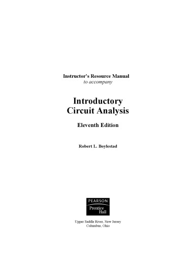
(Ebook PDF) Introductory Circuit Analysis 11th Edition by Robert Boylestad 1784486833 9781784486839
$50.00 Original price was: $50.00.$25.00Current price is: $25.00.
Introductory Circuit Analysis 11th Edition by Robert L. Boylestad – Ebook PDF Instant Download/DeliveryISBN: 1784486833, 9781784486839
Full download Introductory Circuit Analysis 11th Edition after payment.
Product details:
ISBN-10 : 1784486833
ISBN-13 : 9781784486839
Author: Robert Boylestad
Introductory Circuit Analysis, the number one acclaimed text in the field for over three decades, is a clear and interesting information source on a complex topic. The Thirteenth Edition contains updated insights on the highly technical subject, providing readers with the most current information in circuit analysis. With updated software components and challenging review questions at the end of each chapter, this text engages readers in a profound understanding of Circuit Analysis.
Introductory Circuit Analysis 11th Table of contents:
Chapter 1: Introduction
1.1 The Electrical/Electronics Industry
1.2 A Brief History
The Beginning
The Age of Electronics
The Solid-State Era
1.3 Units of Measurement
1.4 Systems of Units
1.5 Significant Figures, Accuracy, and Rounding Off
1.6 Powers of Ten
1.7 Fixed-Point, Floating-Point, Scientific, and Engineering Notation
Prefixes
1.8 Conversion Between Levels of Powers of Ten
1.9 Conversion Within and Between Systems of Units
1.10 Symbols
1.11 Conversion Tables
1.12 Calculators
TI-89 Calculator
Calculator Fundamentals
1.13 Computer Analysis
Languages
Software Packages
Chapter 2: Voltage and Current
2.1 Introduction
2.2 Atoms and Their Structure
2.3 Voltage
2.4 Current
Safety Considerations
2.5 Voltage Sources
Batteries
Solar Cell
Generators
Power Supplies
Fuel Cells
2.6 Ampere-Hour Rating
2.7 Battery Life Factors
2.8 Conductors and Insulators
2.9 Semiconductors
2.10 Ammeters and Voltmeters
2.11 Applications
Flashlight
12 V Car Battery Charger
Answering Machines/Phones dc Supply
2.12 Computer Analysis
Chapter 3: Resistance
3.1 Introduction
3.2 Resistance: Circular Wires
Circular Mils (CM)
3.3 Wire Tables
3.4 Temperature Effects
Conductors
Semiconductors
Insulators
Temperature Coefficient of Resistance
PPM/°c
3.5 Types of Resistors
Fixed Resistors
Maximum Voltage Rating
Variable Resistors
3.6 Color Coding and Standard Resistor Values
Surface Mount Resistors
3.7 Conductance
3.8 Ohmmeters
3.9 Resistance: Metric Units
3.10 The Fourth Element—The Memristor
3.11 Superconductors
3.12 Thermistors
3.13 Photoconductive Cell
3.14 Varistors
3.15 Applications
Electric Baseboard Heating Element
Dimmer Control in an Automobile
Strain Gauges
Chapter 4: Ohm’s Law, Power, and Energy
4.1 Introduction
4.2 Ohm’s Law
4.3 Plotting Ohm’s Law
4.4 Power
4.5 Energy
4.6 Efficiency
4.7 Circuit Breakers, GFCIs, and Fuses
4.8 Applications
Fluorescent versus CFL and LED Bulbs
Microwave Oven
Household Wiring
4.9 Computer Analysis
PSpice
Multisim
Chapter 5: Series dc Circuits
5.1 Introduction
5.2 Series Resistors
Analogies
Instrumentation
5.3 Series Circuits
Analogies
Instrumentation
5.4 Power Distribution in a Series Circuit
5.5 Voltage Sources in Series
Instrumentation
5.6 Kirchhoff’s Voltage Law
5.7 Voltage Division in a Series Circuit
Voltage Divider Rule (VDR)
5.8 Interchanging Series Elements
5.9 Notation
Voltage Sources and Ground
Double-Subscript Notation
Single-Subscript Notation
General Comments
5.10 Ground Connection Awareness
5.11 Voltage Regulation and the Internal Resistance of Voltage Sources
5.12 Loading Effects of Instruments
5.13 Protoboards (Breadboards)
5.14 Applications
Series Control
Holiday Lights
Microwave Oven
Series Alarm Circuit
5.15 Computer Analysis
PSpice
Multisim
Chapter 6: Parallel dc Circuits
6.1 Introduction
6.2 Parallel Resistors
Special Case: Two Parallel Resistors
Analogies
Instrumentation
6.3 Parallel Circuits
Instrumentation
6.4 Power Distribution in a Parallel Circuit
6.5 Kirchhoff’s Current Law
6.6 Current Divider Rule
Special Case: Two Parallel Resistors
6.7 Voltage Sources in Parallel
6.8 Open and Short Circuits
6.9 Voltmeter Loading Effects
6.10 Summary Table
6.11 Troubleshooting Techniques
6.12 Protoboards (Breadboards)
6.13 Applications
Car System
House Wiring
Parallel Computer Bus Connections
6.14 Computer Analysis
PSpice
Multisim
Chapter 7: Series-Parallel Circuits
7.1 Introduction
7.2 Series-Parallel Networks
7.3 Reduce and Return Approach
7.4 Block Diagram Approach
7.5 Descriptive Examples
7.6 Ladder Networks
7.7 Voltage Divider Supply (Unloaded and Loaded)
No-Load Conditions
Loaded Conditions
7.8 Potentiometer Loading
7.9 Impact of Shorts and Open Circuits
7.10 Ammeter, Voltmeter, and Ohmmeter Design
The Ammeter
The Voltmeter
The Ohmmeter
7.11 Applications
Boosting a Car Battery
Electronic Circuits
7.12 Computer Analysis
PSpice
Chapter 8: Methods of Analysis and Selected Topics (dc)
8.1 Introduction
8.2 Current Sources
Introduction
Source Conversions
Current Sources in Parallel
Current Sources in Series
8.3 Branch-Current Analysis
Branch-Current Analysis Procedure
8.4 Mesh Analysis (General Approach)
Mesh Analysis Procedure
Supermesh Currents
8.5 Mesh Analysis (Format Approach)
Mesh Analysis Procedure
8.6 Nodal Analysis (General Approach)
Supernode
8.7 Nodal Analysis (Format Approach)
Nodal Analysis Procedure
8.8 Bridge Networks
TI-89 Calculator Solution
8.9 Y-Δ (T-π) and Δ-Y (π-T) Conversions
8.10 Applications
Constant-Current Alarm Systems
Wheatstone Bridge Smoke Detector
Schematic with Nodal Voltages
8.11 Computer Analysis
PSpice
Multisim
Chapter 9: Network Theorems
9.1 Introduction
9.2 Superposition Theorem
9.3 Thévenin’s Theorem
Thévenin’s Theorem Procedure
Experimental Procedures
9.4 Norton’s Theorem
Norton’s Theorem Procedure
Experimental Procedure
9.5 Maximum Power Transfer Theorem
9.6 Millman’s Theorem
9.7 Substitution Theorem
9.8 Reciprocity Theorem
9.9 Computer Analysis
PSpice
Multisim
Chapter 10: Capacitors
10.1 Introduction
10.2 The Electric Field
10.3 Capacitance
10.4 Capacitors
Capacitor Construction
Types of Capacitors
Leakage Current and ESR
Temperature Effects: ppm
Capacitor Labeling
Measurement and Testing of Capacitors
Standard Capacitor Values
10.5 Transients in Capacitive Networks: The Charging Phase
The Concept of t(0-) and t(0+)
Using the Calculator to Solve Exponential Functions
10.6 Transients in Capacitive Networks: The Discharging Phase
The Effect of τ on the Response
10.7 Initial Conditions
10.8 Instantaneous Values
10.9 Thévenin Equivalent: τ = RThC
10.10 The Current iC
10.11 Capacitors in Series and in Parallel
10.12 Energy Stored by a Capacitor
10.13 Stray Capacitances
10.14 Applications
Touch Pad
Surge Protector (Line Conditioner)
10.15 Computer Analysis
PSpice
Multisim
Chapter 11: Inductors
11.1 Introduction
11.2 Magnetic Field
11.3 Inductance
Inductor Construction
Types of Inductors
Practical Equivalent Inductors
Inductor Labeling
Measurement and Testing of Inductors
11.4 Induced Voltage vL
11.5 R-L Transients: The Storage Phase
11.6 Initial Conditions
11.7 R-L Transients: The Release Phase
11.8 Thévenin Equivalent: τ = L/RTh
11.9 Instantaneous Values
11.10 Average Induced Voltage: vLav
11.11 Inductors in Series and in Parallel
11.12 Steady-State Conditions
11.13 Energy Stored by an Inductor
11.14 Applications
Household Dimmer Switch
11.15 Computer Analysis
PSpice
Multisim
Chapter 12: Magnetic Circuits
12.1 Introduction
12.2 Magnetic Field
12.3 Reluctance
12.4 Ohm’s Law for Magnetic Circuits
12.5 Magnetizing Force
12.6 Hysteresis
12.7 Ampère’s Circuital Law
12.8 Flux ɸ
12.9 Series Magnetic Circuits: Determining NI
12.10 Air Gaps
12.11 Series-Parallel Magnetic Circuits
12.12 Determining ɸ
12.13 Applications
Speakers and Microphones
Hall Effect Sensor
Magnetic Reed Switch
Magnetic Resonance Imaging
Chapter 13: Sinusoidal Alternating Waveforms
13.1 Introduction
13.2 Sinusoidal ac Voltage Characteristics and Definitions
Generation
Definitions
13.3 Frequency Spectrum
Defined Polarities and Direction
13.4 The Sinusoidal Waveform
13.5 General Format for the Sinusoidal Voltage or Current
Calculator Operations
13.6 Phase Relations
Function Generators
The Oscilloscope
13.7 Average Value
Instrumentation
13.8 Effective (rms) Values
DC + AC
True rms Meters
13.9 Converters and Inverters
13.10 ac Meters and Instruments
Iron-Vane or d’Arsonval Movement
Electrodynamometer Movement
Frequency Counter
Clamp-on Meters
Impedance Measurements
13.11 Applications
(120 V at 60 Hz) versus (220 V at 50 Hz)
Safety Concerns (High Voltages and dc versus ac)
13.12 Computer Analysis
PSpice
Multisim
Chapter 14: The Basic Elements and Phasors
14.1 Introduction
14.2 Response of Basic R, L, and C Elements to a Sinusoidal Voltage or Current
Resistor
Inductor
Capacitor
14.3 Frequency Response of the Basic Elements
Ideal Response
Practical Response
14.4 Average Power and Power Factor
Resistor
Inductor
Capacitor
Power Factor
14.5 Complex Numbers
14.6 Rectangular Form
14.7 Polar Form
14.8 Conversion Between Forms
14.9 Mathematical Operations with Complex
Complex Conjugate
Reciprocal
Addition
Subtraction
Multiplication
14.10 Calculator Methods with Complex Numbers
Calculators
14.11 Phasors
14.12 Computer Analysis
PSpice
Multisim
Chapter 15: Series AC Circuits
15.1 Introduction
15.2 Resistive Elements
15.3 Inductive Elements
15.4 Capacitive Elements
15.5 Impedance Diagram
15.6 Series Configuration
15.7 Voltage Divider Rule
15.8 Frequency Response for Series ac Circuits
Series R-C ac Circuit
The Total Impedance ZT
The Voltage Vc
Series R-L ac Circuit
Series R-L-C Circuit
15.9 Summary: Series ac Circuits
15.10 Phase Measurements
15.11 Applications
Speaker Systems
15.12 Computer Analysis
PSpice
Multisim
Chapter 16: Parallel AC Circuits
16.1 Introduction
16.2 Total Impedance
16.3 Total Admittance
16.4 Parallel ac Networks
16.5 Current Divider Rule
16.6 Frequency Response of Parallel Elements
Parallel R-L ac Network
The Impedance ZT
The Source Current Is
Parallel R-C ac Network
The Source Current Is
Parallel R-L-C Network
16.7 Summary: Parallel ac Networks
16.8 Equivalent Circuits
16.9 Applications
Home Wiring
Phase-Shift Power Control
16.10 Computer Analysis
PSpice
Multisim
Chapter 17: Series-Parallel AC Networks
17.1 Introduction
17.2 Illustrative Examples
17.3 Ladder Networks
17.4 Grounding
17.5 Applications
GFCI (Ground Fault Circuit Interrupter)
17.6 Computer Analysis
PSpice
Multisim
Chapter 18: Methods of Analysis and Selected Topics (AC)
18.1 Introduction
18.2 Independent Versus Dependent (Controlled) Sources
18.3 Source Conversions
Independent Sources
Dependent Sources
18.4 Mesh Analysis
General Approach
Format Approach
18.5 Nodal Analysis
General Approach
Format Approach
18.6 Bridge Networks (ac)
18.7 Δ-Y, Y-Δ Conversions
18.8 Computer Analysis
PSpice
Multisim
Chapter 19: Network Theorems (AC)
19.1 Introduction
19.2 Superposition Theorem
Independent dc and ac Sources
Dependent ac Sources
19.3 Thévenin’s Theorem
Independent ac and dc Sources
Dependent Sources
19.4 Norton’s Theorem
Independent ac and dc Sources
Dependent ac Sources
19.5 Maximum Power Transfer Theorem
19.6 Substitution, Reciprocity, and Millman’s Theorems
19.7 Application
Electronic Systems
19.8 Computer Analysis
PSpice
Multisim
Chapter 20: Power (AC)
20.1 Introduction
20.2 General Equation
20.3 Resistive Circuit
20.4 Apparent Power
20.5 Inductive Circuit and Reactive Power
20.6 Capacitive Circuit
20.7 The Power Triangle
20.8 The Total P, Q, and S
20.9 Power-Factor Correction
20.10 Power Meters
20.11 Effective Resistance
Experimental Procedure
Radiation Losses
Skin Effect
Hysteresis and Eddy Current Losses
20.12 Applications
Portable Power Generators
Business Sense
20.13 Computer Analysis
PSpice
Chapter 21: Resonance
21.1 Introduction
21.2 Series Resonant Circuit
21.3 The Quality Factor (Q)
21.4 ZT Versus Frequency
21.5 Selectivity
21.6 VR, VL, and VC
21.7 Practical Considerations
21.8 Summary
21.9 Examples (Series Resonance)
21.10 Parallel Resonant Circuit
21.11 Selectivity Curve for Parallel Resonant Circuits
21.12 Effect of Qi ≥ 10
21.13 Summary Table
21.14 Examples (Parallel Resonance)
21.15 Applications
Stray Resonance
Graphic and Parametric Equalizers
21.16 Computer Analysis
PSpice
Multisim
Chapter 22: Decibels, Filters, and Bode Plots
22.1 Introduction
Logarithms
Positive Impact of Logarithmic Plots
22.2 Properties of Logarithms
Calculator Functions
22.3 Decibels
Power Gain
Voltage Gain
Human Auditory Response
Instrumentation
22.4 Filters
22.5 R-C Low-Pass Filter
22.6 R-C High-Pass Filter
22.7 Band-Pass Filters
22.8 Band-Stop Filters
22.9 Double-Tuned Filter
22.10 Other Filter Configurations
22.11 Bode Plots
High-Pass R-C Filter
22.12 Sketching the Bode Response
22.13 Low-Pass Filter with Limited Attenuation
22.14 High-Pass Filter with Limited Attenuation
22.15 Additional Properties of Bode Plots
22.16 Crossover Networks
22.17 Applications
Attenuators
Noise Filters
22.18 Computer Analysis
PSpice
Multisim
Chapter 23: Transformers
23.1 Introduction
23.2 Mutual Inductance
23.3 The Iron-Core Transformer
23.4 Reflected Impedance and Power
23.5 Impedance Matching, Isolation, and Displacement
23.6 Equivalent Circuit (Iron-Core Transformer)
23.7 Frequency Considerations
23.8 Series Connection of Mutually Coupled Coils
23.9 Air-Core Transformer
23.10 Nameplate Data
23.11 Types of Transformers
23.12 Tapped and Multiple-Load Transformers
23.13 Networks with Magnetically Coupled Coils
23.14 Current Transformers
23.15 Applications
Soldering Gun
Low-Voltage Compensation
Ballast Transformer
Recent Developments
23.16 Computer Analysis
PSpice
Multisim
Chapter 24: Polyphase Systems
24.1 Introduction
24.2 Three-Phase Generator
24.3 Y-Connected Generator
24.4 Phase Sequence (Y-Connected Generator)
24.5 Y-Connected Generator with a Y-Connected Load
24.6 Y-Δ System
24.7 Δ-Connected Generator
24.8 Phase Sequence (Δ-Connected Generator)
24.9 Δ-Δ, Δ-Y Three-Phase Systems
24.10 Power
Y-Connected Balanced Load
Δ-Connected Balanced Load
24.11 Three-Wattmeter Method
24.12 Two-Wattmeter Method
24.13 Unbalanced, Three-Phase, Four-Wire, Y-Connected Load
24.14 Unbalanced, Three-Phase, Three-Wire, Y-Connected Load
24.15 Residential and Industrial Service Distribution Systems
Chapter 25: Pulse Waveforms and the R-C Response
25.1 Introduction
25.2 Ideal Versus Actual
Amplitude
Pulse Width
Base-Line Voltage
Positive-Going and Negative-Going Pulses
Rise Time (tr) and Fall Time (tf)
Tilt
25.3 Pulse Repetition Rate and Duty Cycle
25.4 Average Value
25.5 Transient R-C Networks
25.6 R-C Response to Square-Wave Inputs
25.7 Oscilloscope Attenuator and Compensating Probe
25.8 Application
TV Remote
25.9 Computer Analysis
PSpice
Chaptre 26: Nonsinusoidal Circuits
26.1 Introduction
26.2 Fourier Series
Average Value: A0
Odd Function (Point Symmetry)
Even Function (Axis Symmetry)
Mirror or Half-Wave Symmetry
Repetitive on the Half-Cycle
Mathematical Approach
Instrumentation
26.3 Fourier Expansion of a Square Wave
26.4 Fourier Expansion of a Half-Wave Rectified Waveform
26.5 Fourier Spectrum
26.6 Circuit Response to a Nonsinusoidal Input
Instrumentation
26.7 Addition and Subtraction of Nonsinusoidal Waveforms
26.8 Computer Analysis
People also search for Introductory Circuit Analysis 11th:
introductory circuit analysis solutions
introductory circuit analysis 10th edition solution
introductory circuit analysis 13th edition answers
introductory circuit analysis 11th edition answers
introductory circuit analysis analysis
Tags:
Introductory,Circuit Analysis,Robert Boylestad
You may also like…
Uncategorized
Instructor Manual for Corrections: The Essentials 2nd Second Edition, Mary K. Stohr, Anthony Walsh
Engineering - Electrical & Electronic Engineering
Introductory CIrcuIt AnalysIs, 14th Global Edition by Robert L. Boylestad
Education Studies & Teaching - School Education & Teaching
Weaving It Together: Instructor S Manual (books 3 And 4) 3rd Edition Milada Broukal
Engineering - Electrical & Electronic Engineering
Introductory Circuit Analysis. (Global Edition) (14th Ed.) Robert L. Boylestad
Engineering - Electrical & Electronic Engineering
Engineering - Electrical & Electronic Engineering
Engineering Circuit Analysis, 10e 10th Edition William H. Hayt
Engineering - Electrical & Electronic Engineering
Technique - Electronics
Instructor’s Resource Manual to accompany Electronic Devices And Circuit Theory 10th Edition Robert
Uncategorized


