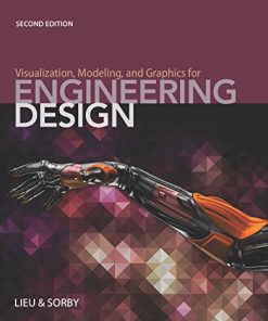
(Ebook PDF) Visualization Modeling and Graphics for Engineering Design 2nd edition by Dennis Lieu, Sheryl Sorby 1285172957 978-1285172958 full chapters
$50.00 Original price was: $50.00.$25.00Current price is: $25.00.
Visualization, Modeling, and Graphics for Engineering Design 2nd edition by Dennis Lieu, Sheryl Sorby – Ebook PDF Instant Download/DeliveryISBN: 1285172957, 978-1285172958
Full download Visualization, Modeling, and Graphics for Engineering Design 2nd edition after payment.
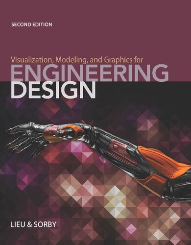
Product details:
ISBN-10 : 1285172957
ISBN-13 : 978-1285172958
Author: Dennis Lieu, Sheryl Sorby
Created for the next generation of engineering professionals, VISUALIZATION, MODELING, AND GRAPHICS FOR ENGINEERING DESIGN, Second Edition, combines coverage of traditional drafting essentials and the cutting-edge technology and methods today’s professionals need to master for career success. This versatile text provides a strong grounding in fundamentals including core design skills, geometric dimensioning and tolerancing, sketching and drawing, and industry- and discipline-specific applications, even while recognizing how computers have enabled visualizing and modeling techniques that have changed the engineering design process.
Visualization, Modeling, and Graphics for Engineering Design 2nd Table of contents:
Cover Page
Title Page
Copyright Page
Preface
Acknowledgments
About the authors
Section One. Laying the Foundation
Chapter 1. An Introduction to Graphical Communication in Engineering
1.01. Introduction
1.02. A Short History
1.02.01. Ancient History
1.02.02. The Medieval Period
1.02.03. The Renaissance
1.02.04. The Industrial Revolution
1.02.05. More Recent History
1.03. Engineering Graphics Technology
1.03.01. Early Years
1.03.02. Instrument Drawing
1.03.03. The Computer Revolution
1.03.04. Graphics as a Design Tool
1.03.05. Graphics as an Analysis Tool
1.03.06. Graphics as a Presentation Tool
1.04. The Modern Role of Engineering Graphics
1.05. Chapter Summary
1.06. Glossary of Key Terms
1.07. Questions for Review
1.08. Problems
Chapter 2. Sketching
2.01. Introduction
2.02. Sketching in the Engineering Design Process
2.03. Sketching Lines
2.04. Sketching Curved Entities
2.05. Construction Lines
2.06. Coordinate Systems
2.07. Isometric Sketches of Simple Objects
2.07.01. Circles in Isometric Sketches
2.07.02. Circular Holes in Isometric Sketches
2.08. Oblique Pictorials
2.08.01. Circular Holes in Oblique Pictorial Sketches
2.09. Shading and Other Special Effects
2.10. Sketching Complex Objects
2.11. Chapter Summary
2.12. Glossary of Key Terms
2.13. Questions for Review
2.14. Problems
Chapter 3. Visualization
3.01. Introduction
3.02. Background
3.03. Development of Spatial Skills
3.04. Types of Spatial Skills
3.05. Assessing Spatial Skills
3.06. The Importance of Spatial Skills
3.07. Isometric Corner Views of Simple Objects
3.08. Object Rotations about a Single Axis
3.08.01. Notation
3.08.02. Rotation of Objects by More Than 90 Degrees about a Single Axis
3.08.03. Equivalencies for Rotations about a Single Axis
3.09. Rotation about Two or More Axes
3.09.01. Equivalencies for Object Rotations about Two or More Axes
3.10. Reflections and Symmetry
3.10.01. Symmetry
3.11. Cross Sections of Solids
3.12. Combining Solids
3.13. Chapter Summary
3.14. Glossary of Key Terms
3.15. Questions for Review
3.16. Problems
Chapter 4. Creativity and the Design Process
4.01. Introduction
4.02. What Is Design?
4.02.01. Computers in Design
4.02.02. Classification of Engineering Designers
4.03. Creativity in Design
4.03.01. Visual Thinking
4.03.02. Brainstorming
4.03.03. Brainwriting (6-3-5 Method)
4.03.04. Morphological Charts
4.03.05. Concept Mapping
4.04. The Engineering Design Process
4.04.01. Stage 1: Problem Identification
4.04.02. Stage 2: Concept Generation
4.04.03. Stage 3: Concept Selection and Refinement
4.04.04. Stage 4: Design Evaluation and Analysis
4.04.05. Stage 5: Physical Prototyping
4.04.06. Stage 6: Design Documentation
4.04.07. Stage 7: Production
4.05. The Concurrent Engineering Design Process
4.06. Chapter Summary
Case Study. Integrated Project: Conception of the Hoyt AeroTec Target Bow
4.07. Glossary of Key Terms
4.08. Questions for Review
4.09. Design Projects
Design Project #1: Escape!
Design Project #2: Fast Food!
Design Project #3: Reward!
Design Project #4: Deploy It!
Design Project #5: Vertical Limit
Design Project #6: There ‘N Back
Section Two. Modern Design Practice and Tools
Chapter 5. Solid Modeling
5.01. Introduction
5.02. Tools for Developing Your Idea
5.02.01. Two-Dimensional CAD
5.02.02. Wireframe Modeling
5.02.03. Surface Modeling
5.02.04. Solid Modeling
5.03. A Parametric Solid Model
5.03.01. Valid Profiles
5.03.02. Creation of the Solid
5.04. Making It Precise
5.04.01. Orientation of the Sketch
5.04.02. Geometric Constraints
5.04.03. Dimensional Constraints
5.04.04. Uniqueness of Constraints
5.04.05. Associative and Algebraic Constraints
5.05. Strategies for Combining Profile Constraints
5.06. More Complexity Using Constructive Solids
5.07. Breaking It Down into Features
5.07.01. The Base Feature
5.07.02. Chamfers, Rounds, and Fillets
5.07.03. Holes
5.07.04. Shells
5.07.05. Ribs and Webs
5.07.06. Other Feature Types
5.07.07. Cosmetic Features
5.07.08. An Understanding of Features and Functions
5.08. More Ways to Create Sophisticated Geometry
5.08.01. Defining Datum Points
5.08.02. Defining Datum Axes
5.08.03. Defining Datum Planes
5.08.04. Chaining Datums
5.08.05. Using Arrays (Rectangular and Circular)
5.08.06. Using Mirrored Features
5.08.07. Using Blends
5.08.08. Sweeps
5.09. The Model Tree
5.10. Families of Parts
5.11. Extraction of 2-D Drawings
5.12. Chapter Summary
5.13. Glossary of Key Terms
5.14. Questions for Review
5.15. Problems
Chapter 6. Assembly Modeling
6.01. Introduction
6.02. Assembly Terminology
6.02.01. Associativity
6.03. Assembly Hierarchy
6.04. Assembly Constraints
6.04.01. Concentric Constraints
6.04.02. Mating Surfaces Constraints
6.04.03. Coincident Constraints
6.04.04. Distance Constraints
6.04.05. Adding Constraints to Your Assembly
6.05. Exploded Configurations
6.06. Interferences and Clearances
6.07. Bill of Materials
6.08. Assembly Strategy
6.08.01. Bottom-Up Assembly Modeling
6.08.02. Top-Down Assembly Modeling
6.09. Strategy for Bottom-up Assembly Modeling
6.10. Chapter Summary
6.11. Glossary of Key Terms
6.12. Questions for Review
6.13. Problems
Chapter 7. Design Analysis
7.01. Introduction
7.02. Reverse Engineering
7.03. Metrology Tools for Reverse Engineering
7.03.01. Handheld Calipers
7.03.02. Coordinate Measuring Machine (CMM)
7.03.03. 3-D Laser Scanner
7.04. The Reverse Engineering Process
7.04.01. Defining the Reverse Engineering Project
7.04.02. Dissecting a System
7.04.03. Obtaining Part Sizes
7.04.04. Developing a 3-D CAD Model
7.04.05. Considering Potential Redesign
7.05. Geometric Properties Analysis
7.05.01. Measurement Analysis
7.05.02. Mass Properties Analysis
7.06. Finite Element Analysis
7.06.01. Classes of FEA Problems
7.06.02. Finite Element Meshes
7.06.03. Finite Element Boundary Conditions
7.06.04. Finite Element Output
7.07. Chapter Summary
7.08. Glossary of Key Terms
7.09. Questions for Review
7.10. Problems
Section Three. Setting Up an Engineering Drawing
Chapter 8. Orthogonal Projection and Multiview Representation
8.01. Introduction
8.02. A More Precise Way to Communicate Your Ideas
8.02.01. Problems with Pictorials
8.02.02. Viewing Planes
8.02.03. Orthogonal Projection
8.02.04. A Distorted Reality
8.02.05. Choice of Viewing Planes
8.02.06. Size and Alignment
8.03. The Glass Box
8.03.01. Standard Views
8.03.02. The Preferred Configuration
8.04. The Necessary Details
8.04.01. Hidden Lines and Centerlines
8.04.02. The Necessary Views
8.04.03. Hidden Lines versus More Views
8.05. First-Angle Projection versus Third-Angle Projection
8.06. Breaking the Rules—and Why It Is Good to Break Them Sometimes
8.06.01. Threaded Parts
8.06.02. Features with Small Radii
8.06.03. Small Cutouts on Curved Surfaces
8.06.04. Small Intersections with Curved Surfaces
8.06.05. Symmetrical Features
8.06.06. Representation of Welds
8.07. When Six Views Are Not Enough
8.07.01. Features at Odd Angles
8.07.02. Internal Features
8.08. Considerations for 3-D Modeling
8.09. Chapter Summary
8.10. Glossary of Key Terms
8.11. Questions for Review
8.12. Problems
Chapter 9. Pictorial Drawings
9.01. Introduction
9.02. Types of Pictorial Drawings
9.03. Axonometric Drawings
9.03.01. Isometric Drawings
9.03.02. Inclined Surfaces
9.03.03. Oblique Surfaces
9.03.04. Cylindrical Surfaces
9.03.05. Ellipses on Inclined Surfaces
9.04. Oblique Drawings
9.04.01. Types of Oblique Drawings
9.04.02. Construction of Oblique Drawings
9.04.03. Construction of an Object with Circular Features
9.05. Perspective Drawings
9.05.01. Types of Perspective Drawings
9.05.02. Two-Point Perspective Drawings
9.05.03. Construction of a Two-Point Perspective Drawing
9.05.04. Complex Object in Two-Point Perspective
9.06. Considerations for 3-D Modeling
9.07. Chapter Summary
9.08. Glossary of Key Terms
9.09. Questions for Review
9.10. Problems
Chapter 10. Section Views
10.01. Introduction
10.02. A Look Inside
10.03. Full Sections
10.04. What Happens to the Hidden Lines?
10.05. The Finer Points of Section Lines
10.06. Offset Sections
10.07. Half Sections
10.08. Removed Sections
10.09. Revolved Sections
10.10. Broken-Out Sections
10.11. Sections of Assemblies
10.12. A Few Shortcuts to Simplify Your Life
10.12.01. Small Cutouts on Curved Surfaces
10.12.02. Threaded Parts
10.12.03. Thin Features
10.12.04. Vanes, Fins, Spokes, and the Like
10.12.05. Symmetry
10.13. Considerations for 3-D Modeling
10.14. Chapter Summary
10.15. Glossary of Key Terms
10.16. Questions for Review
10.17. Problems
Chapter 11. Auxiliary Views
11.01. Introduction
11.02. Auxiliary Views for Solid Objects
11.03. Auxiliary Views of Irregular or Curved Surfaces
11.04. Creating Auxiliary Views
11.05. Solid Modeling Considerations in Creating Auxiliary Views
11.06. Chapter Summary
11.07. Glossary of Key Terms
11.08. Questions for Review
11.09. Problems
Section Four. Drawing Annotation and Design Implementation
Chapter 12. Dimensioning
12.01. Introduction
12.02. Is the Dimension I See on a Drawing Exact?
12.03. What Are the Rules for Dimensioning?
12.03.01. Millimeters, Inches, or Angstroms?
12.03.02. Types of Dimensioning
12.03.03. Fundamental Rules for Dimensioning
12.04. Definitions
12.05. Redundancy Is Dumb
12.06. Geometrically Correct, but Still Wrong!
12.06.01. Different Ways of Specifying the Same Geometry
12.06.02. Identifying and Specifying the Critical Dimensions for Part Function
12.06.03. Baseline versus Chain Dimensioning
12.06.04. What Types of Dimensions Can Be Measured and Checked?
12.07. Guidelines to Guide Your Lines
12.07.01. Solid Lines Only
12.07.02. Placement and Spacing
12.07.03. Font
12.08. Shortcuts
12.08.01. Diameters and Radii
12.08.02. Chamfers
12.08.03. Standard Machined Holes: Countersinks and Counterbores
12.08.04. Slots
12.09. Notes
12.09.01. General Notes
12.09.02. Local Notes
12.10. Considerations for 3-D Modeling
12.11. Dimensions for the Plate Example
12.12. Fundamental Rules for Dimensioning
12.13. Chapter Summary
12.14. Glossary of Key Terms
12.15. Questions for Review
12.16. Problems
Chapter 13. Tolerancing
13.01. Introduction
13.01.01. Relationships between Different Parts
13.01.02. Problems with Inexperience in New Engineers
13.02. Formats for Tolerances
13.03. Tolerance Buildup Problems
13.03.01. Tolerance Buildup with Chain, Baseline, and Direct Dimensioning
13.03.02. Statistical Tolerance Control
13.04. Use of Tables for Fits
13.04.01. Types of Fits
13.04.02. Fit Terminology
13.04.03. English Fits
13.04.04. Metric Fits
13.04.05. Fits Tables
13.05. Conventional Tolerancing versus Geometric Tolerancing
13.05.01. Features With and Without Size
13.05.02. Conventional Tolerancing and Form
13.05.03. Location of Holes and Pins with Conventional Tolerancing
13.06. Geometric Dimensioning and Tolerancing (GD&T)
13.06.01. The Datum Reference Frame
13.06.02. Geometry Characteristic Symbols and Feature Control Frames
13.06.03. Order of Precedence for Datums
13.06.04. Position Tolerances versus Conventional Tolerances
13.06.05. Form Tolerances
13.06.06. Profile Tolerances
13.06.07. Orientation Tolerances
13.06.08. Location Tolerances
13.06.09. Runout Tolerances
13.07. Chapter Summary
13.08. Glossary of Key Terms
13.09. Questions for Review
13.10. Problems
Chapter 14. Working Drawings
14.01. Introduction
14.02. Making It Formal
14.03. Sheet Sizes
14.04. The Formal Drawing Header in Manufacturing Drawings
14.05. The Drawing Area for Manufactured Parts
14.05.01. Geometry Presentation
14.05.02. Object Views
14.05.03. Notes
14.06. Parts, Subassemblies, and Assemblies
14.06.01. Exploded Assembly Drawings
14.06.02. Outline Assembly Drawings
14.06.03. Sectioned Assembly Drawings
14.06.04. The Bill of Materials
14.06.05. Manufacturing Detail Drawings
14.06.06. More Examples of Manufacturing Drawings
14.07. Construction Drawings
14.07.01. Why Construction Drawings Are Different from Manufacturing Drawings
14.07.02. How Construction Drawings Are Different from Manufacturing Drawings
14.08. Construction Plans
14.08.01. Cover Sheet
14.08.02. Site Plan
14.08.03. Elevation Views
14.08.04. Foundation and Floor Plans
14.08.05. Sections
14.08.06. Detail Construction Drawings
14.08.07. Plan and Profile Drawings
14.09. Engineering Scales
14.09.01. Engineer’s Scale
14.09.02. Metric Scale
14.09.03. Architect’s Scale
14.10. Considerations for 3-D Modeling
14.11. Chapter Summary
14.12. Glossary of Key Terms
14.13. Questions for Review
14.14. Problems
Chapter 15. Working in a Team Environment
15.01. Introduction
15.02. Why Work in a Group?
15.03. What Does It Mean to Be a Team Player?
15.04. Differences between Teaming in the Classroom and Teaming in the Real World
15.05. Team Roles
15.06. Characteristics of an Effective Team
15.06.01. Decisions Made by Consensus
15.06.02. Everyone Participates
15.06.03. Professional Meetings
15.07. Project Organization—Defining Tasks and Deliverables
15.08. Time Management—Project Scheduling
15.08.01. Gantt Charts
15.08.02. Critical Path Method
15.09. Communication
15.09.01. Agreeing How to Communicate
15.09.02. Communicating Outside Meetings
15.09.03. Communicating with the Outside World
15.10. Tools for Dealing with Personnel Issues
15.10.01. Team Contract
15.10.02. Publication of the Rules
15.10.03. Signature Sheet and Task Credit Matrix
15.11. Chapter Summary
15.12. Glossary of Key Terms
Chapter 16. Fabrication Processes
16.01. Introduction
16.02. Making Sure It Can Be Made
16.03. Processes for Low-Volume Production
16.03.01. Standard Commercial Shapes
16.03.02. Sawing
16.03.03. Turning
16.03.04. Drilling
16.03.05. Milling
16.03.06. Electric Discharge Machining
16.03.07. Broaching
16.03.08. Rapid Prototyping
16.03.09. Welding and Brazing
16.03.10. Grinding
16.04. Processes for Higher-Volume Production
16.04.01. Sand Casting
16.04.02. Extrusion
16.04.03. Drawing
16.04.04. Rolling
16.04.05. Die Casting and Molding
16.04.06. Forging
16.04.07. Stamping
16.04.08. Sintering
16.05. Burr Removal
16.06. Combined Processes
16.06.01. Example 1: The Retainer
16.06.02. Example 2: The Coupling
16.06.03. Example 3: The Motor Plate
16.07. Considerations for 3-D Modeling
16.08. Chapter Summary
16.09. Glossary of Key Terms
Chapter 17. Advanced Visualization Techniques
17.01. Introduction
17.02. Basic Concepts and Terminology in Visualization
17.03. The Possibilities for a Feature Representation
17.04. Other Viewpoints
17.05. Advanced Visualization Techniques
17.05.01. Visualization with Basic Concepts
17.05.02. Strategy for a Holistic Approach to Constructing Pictorials from Multiview Drawings
17.05.03. Strategy for Constructing Pictorials by Inverse Tracking of Edges and Vertices
17.05.04. Strategy for Constructing Pictorials by Inverse Tracking of Surfaces
17.05.05. Strategy for Improving Spatial Skills through Imagining Successive Cuts to Objects
17.06. Chapter Summary
17.07. Glossary of Key Terms
Chapter 18. Fasteners
18.01. Introduction
18.02. Screw Threads
18.02.01. Thread Terminology
18.02.02. Single and Multiple Threads
18.02.03. Right- and Left-Hand Threads
18.02.04. Thread Standards
18.02.05. Thread Forms
18.03. Thread Cutting
18.04. Modeling Screw Threads
18.04.01. Thread Representations for Drawings
18.04.02. Thread Representation in Solid Models
18.05. Thread Notes
18.05.01. Metric Threads
18.05.02. Unified National Threads
18.05.03. Other Thread Forms
18.05.04. Thread Notes on a Drawing
18.06. Threaded Fasteners
18.06.01. Bolts and Nuts
18.06.02. Machine Screws and Cap Screws
18.06.03. Studs
18.06.04. Design Considerations for Threaded Fasteners
18.06.05. Set Screws
18.06.06. Self-Tapping Screws
18.07. Rivets
18.07.01. Kinds of Rivets
18.08. Washers
18.09. Pins
18.10. Retaining Rings
18.11. Keys
18.12. Snap-Fit Fasteners
18.13. Chapter Summary
18.14. Glossary of Key Terms
Chapter 19. Technical and Engineering Animation
19.01. Introduction
19.02. Animation Process and Technique
19.02.01. The Planning Stage
19.02.02. The Modeling Stage
19.02.03. The Scene Development Stage: Cameras, Lighting, and Rendering
19.02.04. The Animation Stage: Motion and Action
19.02.05. The Output Stage: Editing and Production
19.03. Chapter Summary
19.04. Glossary of Key Terms
Chapter 20. Presentation of Engineering Data
20.01. Introduction
20.02. Anatomy of the Information Graphic
20.03. Formats for Quantitative Data
20.03.01. Bar Charts
20.03.02. Line Charts
20.03.03. Pie Charts
20.03.04. Scatter Plots
20.03.05. Tables
20.04. Diagrams
20.04.01. Business Diagrams
20.04.02. Technical Diagrams
20.04.03. Visual Storytelling Diagrams
20.05. Chapter Summary
20.06. Glossary of Key Terms
Appendix
People also search for Visualization, Modeling, and Graphics for Engineering Design 2nd:
visualization, modeling, and graphics for engineering design
motion graphics vs graphic design
visualization modeling and graphics for engineering design answers
visualization modeling and graphics for engineering design solutions
visualization modeling and graphics for engineering design 2nd edition pdf
Tags:
Dennis Lieu,Sheryl Sorby,engineering,design,modeling,graphics,visualization
You may also like…
Engineering
Visualization, Modeling, and Graphics for Engineering Design 2nd Edition – Ebook PDF Version
Technique - Water Treatment
Engineering - Engineering - General & Miscellaneous
Engineering - Engineering Technology
Uncategorized
Uncategorized
Information Visualization: Perception for Design (Interactive Technologies) – Ebook PDF Version
Business & Economics - Management & Leadership
Business & Economics
This is Not a Leadership Book: 20 Rules for Success 1st Edition


